Showing posts with label ADC. Show all posts

Sunday, 7 June 2020

More work with the Venturi Tube (Mark 4)

In order to test the latest venturi tube properly I have had to recalculate the areas of the different tube sections.  I performed several calculations to find out the areas of the first and second sections of the tube.

2D Cross Section of the Venturi Tube Design (Mark 4)

The blue shaded area is a cylinder.  The formula for calculating the cross sectional area of a cylinder is:


The area of the blue shaded section is therefore:


Which in metres is 0.0138590478.

The area of the red shaded section is a conical frustrum.  The formula for calculating the area of a conical frustrum is (really complicated!) :


I used an online calculator:


Which in metres is 0.00189862567

The red and blue shaded areas combined make up A1:


The grey shaded section is a cylinder. Its cross sectional area (A2) is therefore:


We can now apply the formula for the venturi tube:


We will of course just insert these values into the previously written arduino code.

One of the requirements for this project is to display real time graphs on a small graphical display.  The display I intend to develop with has not arrived yet. In preparation I thought it would be a good idea to look at using Python and matplotlib.

I have been playing with Python and installed Python 3.8.2 and got it added to my path (Windows 10).  I then installed the matplotlib (library for plotting graphs) and watched a few youtube videos and read some tutorials.

I need to create these graphs:


I have the data being delivered from the sensor so this should not be too difficult to achieve.  Helpfully the graphs have scales and axes...

Many people have been requesting access to the 3D print design files:


Well that is enough for now - Take care...Langster!

Saturday, 6 June 2020

Testing the new venturi tube (Mark 4)

After printing the new venturi tube with internal conical sections I have removed the support material and attempted to use it.  There are some design issues which need attention.  I made the pressure port pieces too small and have had to improvise with a couple of plastic M4 nuts glued on.  To be honest that seems to work quite well so I might do that again as its easier that printing connection pieces.

I have guessed at the new internal dimensions within the firmware code as I am unsure of how the formula applies to the conical sections and I cannot find any information as to how to proceed.  Rather than go through all the calculations again I have updated the firmware from my earlier post and performed a quick test.

For documentation purposes I have set the code with the internal dimensions:

A1 = 0.01455 m^3
A2 = 0.001145 m^3

Here are the results:

Raw Data from the ADC - Gain setting 1, positive = inhalation, negative = exhalation

Differential Pressure - much improved sensitivity

The results seem to be much better than the last attempt.  The graphs clearly show inhalation and exhalation and the sensitivity is much improved.  I suspect that with a calibrated pump the accuracy could be improved further. 

As I don't have a calibrated air pump my intention is to improvise with a balloon and a syringe body...

I have a 25 ml syringe body.  I wish I had a bigger volume one but they are very expensive for some reason.  I will fill a balloon with air from the syringe until I have a litre of air.  I will then release the balloon air through the tube and monitor the results on the volumetric flow graph.  If I get 1000 m/s I have a litre per second of air flow.  I would settle for something close.  Another method would be to obtain a calibrated air flow meter and use that to compare to what I have made...however I would still need a uniform volume of air to test and compare with.

The latest Venturi Tube design with face mask and tubing

If we compare the results from the previous venturi tube (Mark 3) we can see that some considerable improvement has been achieved:

  Venturi Mark 3
Venturi Mark 4
 Peak Raw Data Bits
850
 2900
 Peak Differential Pressure
103 Pa    
 342 Pa
 Peak Volumetric Flow
0.06 m^3/s
 0.03 m^3/s
 Peak Velocity of Flow
 7.1 m/s
 21 m/s

The tube's sensitivity has definitely improved.  We need to assess the volumetric flow measurement more closely hence the need for a calibrated air flow.  Once we have that I believe it will be possible to use this design of tube for accurate measurement of air flow.

Once that has been sorted I need to add the BME280 Temperature, pressure and humidity sensor which arrived recently. 

I have also just bought a 3.5 inch serial display...lets hope I can make it work well and it can be upscaled when necessary.


That's all for now - Langster!

Friday, 10 March 2017

Multifunctional Medical Training Device

A blog reader has asked me to help them design and build a medical training device.  The reader is a medical doctor specialising in Pulmonary treatment and training - In the course of their work they measure how much air flow goes in and out of a person's lungs and how that is affected.  The device to be built needs to measure the following things to a reasonable accuracy:
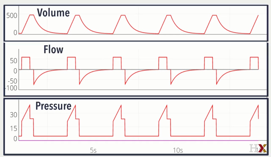
  • Air pressure
  • Air flow
  • Thoracic and Abdominal movement (Using EMG - electromyography)
It would be nice if the device was as accurate as possible, battery powered and wireless as much as possible to make it easy to use and less invasive to the patient.

I'm going to help them by designing something that does all of the above using the arduino microcontroller as the main processor.  The circuit will also have a bluetooth module or ESP8266 wifi module to provide serial communications to an external PC or mobile phone application to display the results.

In order to start the design work we need to assess the instrumentation requirements.  To that end we need to investigate how much air flow and pressure is present in a normal setting and the extreme needed to be measured. From that it should be possible to estimate the requirements for the sensing elements of the device.


The above websites discuss how a medical practitioner performs the above measurements and the associated results expected.  Unhelpfully for an engineer designing equipment the measurement units provided are not clear.  Apparently the results of the testing are quoted as the volume of air inhaled and exhaled in Litres / minute.  So we need a sensor that can measure flow in litres / second or milli-litres per second.  There is no mention of air pressure in those measurements and having had some feedback from the blog reader the pressure measurement is for measuring the pressure from an external ventilator device. The flow probably relates to how much air is ingested into the lungs and the exhaled volume should be slightly lower which indicates how much oxygen was received by the lungs and how much carbon dioxide was produced as part of the operation, We could of course provide sensors for those gases as well. The air pressure would relate to how much a person's diaphragm and chest movement affect the volume of air was inhaled and exhaled and finally this can be corroborated with the EMG measurement.  I don't have much experience with EMG - I made an ECG heart rate monitor many years ago but have mostly forgotten all about it.  EMG is a similar measurement technique.


I am not a pulmonary medical expert so this is conjecture at the moment.  With further discussion I suspect the brief can be expanded upon as required.  For now I will discuss how I intend to implement the device.

The test subject will wear a mask covering the nose and mouth and with tubes attached to the mask which allow the user to breath in and out normally.  Those tubes will be connected to the pressure and flow sensor which in turn will send electronic signal data to an analogue to digital converter which will then pass digital information to a microcontroller (the arduino).  The data received can then be sent out serially and also via Bluetooth or WiFi to an external computer for further processing and graphical display. 

I have no budget for this project so I'm free to choose as I please (I'm paying, so whilst I can choose whatever I like, I'm not a rich person so I'm going to try and cut cost where I can).

The sensors I'm going to use are:

MPS20N0040D-D - I've used it before and I have a pre-designed breakout board (Massive Grin)

MPXV7002DP - I've not used this one before but its easily available with a breakout board and is fairly in-expensive.  I bought mine from ebay for £20
3 Terminal ECG pads and wires - available from Ebay in China at £5.99 for the wires and £5.91 for the pads.

All of these items are available from any good auction website if one looks hard enough:

Ebay - Air Flow Pressure Senor

Ebay - ECG Leads

Ebay - ECG Pads

I'm not sure how physically large the circuit will end up being so I'm not going to specify and enclosure at the moment - Once I have an idea of size I will choose something suitable or design an enclosure that can be 3D printed.

I am currently waiting for parts to arrive from China, once they do I will develop and test the first part of the circuit.

That's all for now - Take care always

Langster!