We were all working on different projects and generally helping each other out - hackspaces are great places for some communal assistance, banter and access to workshop space and tools! If you have one in the local area and are interested in any kind of science or engineering I recommend having a look!
Anyway the lads were trying to get an old electric scooter working. We knew that the motor was working but that the motor driver PCB had failed. So what we needed to do was to make a new driver circuit. We decided to try a few options but without information as to how much power the motor used when in operation and under load we were a bit stuck. So what with being excited and impatient we connected an off the shelf motor driver PCB (I think it was one of these - http://proto-pic.co.uk/l298-dual-h-bridge-motor-driver/?gclid=CL-K47CVzrICFWLHtAodyxIAFA) and wired it up. It did work with a test sketch. We made the motor go forwards for three seconds and backwards for three seconds. There were problems though. The L298 motor controller device became EXCEEDINGLY hot! This was because the motor we were driving had a much higher power rating than the motor driver could provide (Whoops!). We also may have performed a locked rotor test which made the magic smoke appear!!
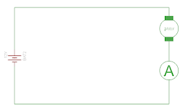
So after letting the steaming pile of junk (motor controller) cool down we removed it and powered the motor straight from a high current DC power supply. We inserted an ammeter into the circuit so we could measure the current draw of the motor when it was running. We also measured the current draw when the motor was stalled (locked rotor test) We found that when the motor was running it drew about 3A which dropped as the motor ran for a while. We found that when we stopped the wheel turning (locked the rotor) we found that the motor drew 19A!!! The circuit diagram for those that are interested is below:
So....what does all this mean?
It means that when the motor is not loaded (Nobody standing on the scooter and the accelerator pushed) the motor will draw 3A of current from the battery (supply). When someone is stood on the scooter the motor will draw more current (lets say 10A - at a guess) and when someone brakes or is going up a steep hill the motor will draw 19A. We need a way of providing at least 10A to the motor but in a controlled manner (we need to be able to control the speed of the scooter!). We also need a way of making sure that the motor cannot draw more than say 16A - this is to prevent the battery being run down in a hurry and to stop any control electronics being burnt out when someone has to brake in a hurry.
Our scooter only needs to go forward so we don't need to use a motor H bridge controller (like the L298 motor driver circuit) we can use a simple transistor driver circuit. We could use a high current bipolar transistor but in this case it is better to use a Field effect transistor.
For those that don't know much about transistors I recommend taking a look at the following websites:
The differences between Bipolar Transistors and Field effect transistors are many and varied. The main differences are:
Bipolar Transistor - also known as a bipolar junction transistor or BJT
A BJT is a current controlled device
A BJT is made up of three different pieces of silicon - with three terminals: Base, Collector and Emittor
Switching speed is slow compared with a FET
Bipolar transistors use less power than a FET
Bipolar transistors are not affected by Static Electricity
More commonly used for low current switching and amplifiers although there are plenty of devices which will perform high current operation.
Field Effect Transistor
A FET is a voltage controlled device
A FET is made up of a single piece of silicon with a channel in the middle (unipolar) but still has three terminals called Gate, Drain and Source.
FETS can switch more quickly than BJTS
FETS are more commonly used for high power operation and switching.
FETS are affected by Static electricity and care should be taken when using them.
So we need an FET to provide the current control for our scooter motor - Lets pick one! How do we go about deciding which one to go for? There are literally thousands.....Lets define some parameters and learn to use the datasheets and parametric searches and choose one that way. This is something every good electronics engineer should be able to do when designing circuits.
So what do we have in our circuit:
A 12V supply
A 200W motor - just a guess
What do we need the circuit to do:
A device to provide current control - it must be able to provide (source) 16A continually between drain and source (IDS) and be able to work with a 12V supply (voltage between drain and source or Vds). In our case we wanted to control the FET from a microcontroller (arduino based) so it has to turn on (voltage between gate and source or Vgs threshold) with 5V. As we were not intending to do any switching with this FET the other parameters aren't too important at this time. Although keeping an eye on the maximum operating temperature and power dissipation is always a good plan! For this device I thought we would use an N-channel enhancement MOSFET. That's a metal oxide semiconductor field effect transistor that requires a positive voltage at the gate to make the transistor conduct between drain and source by opening the channel.....the terminology gets complicated quickly. There is another flavour of MOSFET called N-type depletion that requires a positive voltage to close the channel. Then you can also get P-type FETS as well.....I understand why people find it hard to use FETS....I know I struggle sometimes!
Anyway we have some parameters:
Vds - 12V or higher
Vgs threshold - up to 5V
Ids - 20A or higher
N-Type Enhancement MOSFET
Lets do a search on the farnell website for an N-type Enhancement Mosfet:
It came out with loads of responses!
The cheapest transistor which met our requirements was the IRF540PBF by Vishay Siliconix:
I'm going to use this transistor - Here is the datasheet:
The main reason for me choosing this transistor is....I have some in my junk bin. It meets nearly all of our requirements:
N-Channel
VDS - 100V
VGS Threshold - 4V
IDS - 33A
Power Dissipation - 94W - will need a heat sink!
So what we need to do now is make up a test circuit that shows how this device works and then use it to power our motor. I'm going to use a 12V light bulb as a test load and simulate a circuit. I'm going to use some generic resistor values and then show how to calculate specific resistor values. Here is the circuit:
I'm using a 12V battery, a DC voltage source (will be provided by microcontroller), a 100k resistor - to keep the transistor always turned off, a 1k resistor - to set when the transistor will turn on, a diode to prevent back emf - more on this later and a 12V light bulb like a car headlamp.
As can be seen at the moment because there is no voltage applied at the gate of the FET the light bulb is not turned on and there is only leakage current flowing through the light bulb (12uA). When the gate voltage is increased to 3.9V we can see some current being measured through the light bulb. We would also be able to see the bulb filament glowing dimly.
If we increase the gate voltage further to 3.9V we now start to see some 'proper' current flow at 1.17A through the light bulb (any current flowing greater than an amp is 'proper' current flow in my book!).
Finally if we increase the gate voltage to more than the threshold voltage the light bulb comes fully on and we measure 4.06A flowing through the light bulb.
If we were to increase the gate voltage further to 10V we would find that we would still only get 4.06A at the light bulb. This is because the bulb has a fixed power rating of 50W. It won't draw any more power when supplied with 12V. Our motor has a power rating of 200W so it can draw more power as required depending on the load or torque applied to the motor.I don't say this often....lets do some mathematics! There is a formula for calculating the output voltage from a FET. Here is the formula:
Vout = Vs - (Ids * R1)
where
Vout is the voltage through the bulb
Vs is the supply voltage from the battery
Ids is the current between the drain and source of the FET
We know that Vout is also affected by the gate voltage. When the gate voltage was 1V the current between the drain and the source was 12uA. Lets plug these values into the formula:
Vout = 12V - (12uA * 1000R)
Vout = 11.988V
If we now increase the gate voltage to say 5V we get more current flow and therefore more voltage available at the output:
Vout = 12V - (12mA * 1000R)
Vout = 12V
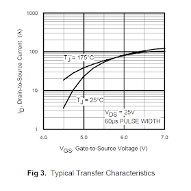
What this shows is that if we re-arrange the formula for R1 we can calculate what value we want for a given voltage output, in order to do this though we need to know what Ids will be for a given Vgs. If we look at the datasheet we can see there is a graph showing Ids over Vgs for a given supply voltage:
R1 = (Vs - Vout) / Ids
So if we want at least 10A (Ids) and 11V (Vout) at the output then we need to select a resistor of:
R1 = (12V - 11V) / 10A
R1 = 0.1R...not really practical, so lets not bother to fit a resistor in this case. We would then get as much current as the supply can provide....
Most datasheets don't provide the graphs for Ids over Vgs at low voltages so it's a guesstimate really. The resistor R1 is more often placed to prevent too much current flowing through the FET when it's in the non-conducting state.
In order to prove this is all real I built the circuit and tested it! Here is the video proof!
Here is a further video of the circuit in operation being used to control a DC motor:
That's it for now. In the next post we will add some current monitoring to the circuit and then implement this as our scooter motor controller!


No comments:
Post a Comment