daGHIZmo's Robot Arm Mk 2
Credit should go to daGHIZmo for the mechanical design which is excellent. I found the robot a little hard to put together but I'm not the best at this sort of thing...it frustrates me sometimes!
Here is the robot in it's full glory:
 |
| The 3D Printed Arm! |
http://langster1980.blogspot.co.uk/2015/04/mearm.html
I found that the current required by the motors was not nearly available. When I designed that shield it was only meant to drive low power servos and not the high torque stuff required here. I also didn't have a great deal of experience in driving servo motors...I hadn't done it for a very long time and truth be told I don't think I have ever done it properly. So in order to use this robot I'm going to have to design a better circuit.
The main issue I'm seeing is that the servo motors are not working because the current draw is too high. I suspect that the 5 Volt regulated arduino supply cannot source the instantaneous current needed to make the servos start moving - once inertia has been overcome the motors are driven quite well...Solution - More POWER!
If we provide an alternative high current 5 volt supply to the servo motors they will work as intended and it will still be possible to power the arduino and everything else required. I also would like to apply some filtering to the servo motor drive connections as I suspect the DC motors used inside the servos are quite poor due to motor brush noise.
Here is the circuit diagram for the Servo Section:
 |
| Servo Connections and Filtering |
 |
| Connectors for Distance sensors and Bluetooth Module and Control Potentiometers |
 |
| Arduino Mega Connections |
 |
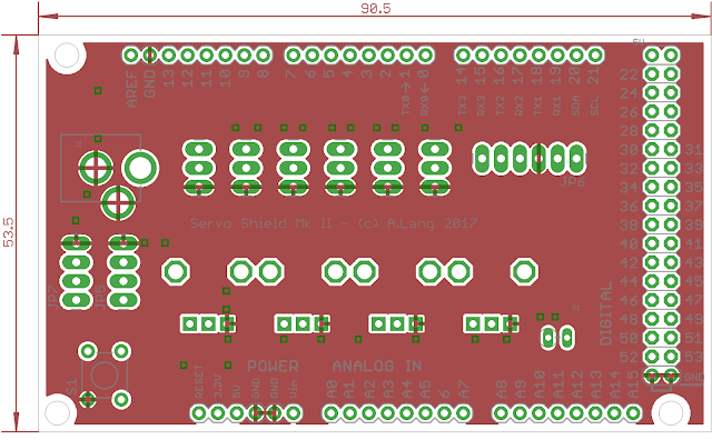
| The Top Layer with dimensions |
 |
| The bottom layer with dimensions |
To make sure every component fits on the board - here is the 3D render:
 |
| 3D model - Top Layer |
 |
| ISO of the 3D model |
That is all for now - Langster!
No comments :
Post a Comment