Showing posts with label Flow Sensor. Show all posts

Sunday, 7 June 2020

More work with the Venturi Tube (Mark 4)

In order to test the latest venturi tube properly I have had to recalculate the areas of the different tube sections.  I performed several calculations to find out the areas of the first and second sections of the tube.

2D Cross Section of the Venturi Tube Design (Mark 4)

The blue shaded area is a cylinder.  The formula for calculating the cross sectional area of a cylinder is:


The area of the blue shaded section is therefore:


Which in metres is 0.0138590478.

The area of the red shaded section is a conical frustrum.  The formula for calculating the area of a conical frustrum is (really complicated!) :


I used an online calculator:


Which in metres is 0.00189862567

The red and blue shaded areas combined make up A1:


The grey shaded section is a cylinder. Its cross sectional area (A2) is therefore:


We can now apply the formula for the venturi tube:


We will of course just insert these values into the previously written arduino code.

One of the requirements for this project is to display real time graphs on a small graphical display.  The display I intend to develop with has not arrived yet. In preparation I thought it would be a good idea to look at using Python and matplotlib.

I have been playing with Python and installed Python 3.8.2 and got it added to my path (Windows 10).  I then installed the matplotlib (library for plotting graphs) and watched a few youtube videos and read some tutorials.

I need to create these graphs:


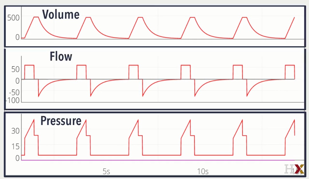
I have the data being delivered from the sensor so this should not be too difficult to achieve.  Helpfully the graphs have scales and axes...

Many people have been requesting access to the 3D print design files:


Well that is enough for now - Take care...Langster!

Thursday, 4 June 2020

Design a better Venturi Tube!


I have looked at the previous post on designing a venturi tube and performed some more research.  It has come to my attention through testing experimentation and research that the venturi design I made is not fit for purpose.  It is unfortunately entirely my fault as to why that is the case.

I didn't do enough research and I didn't listen to my conscience.  I was rushing to get things done...this is what happens when one rushes things.

Rather than dwell on my mistakes I shall design a new and better and hopefully more correct venturi tube.  I wasn't aware of this but there is an ISO standard for venturi tubes.  It is based upon a British Standard:

BS 7405:1991

Unfortunately I cannot look at this standard as I do not have access to it and I cannot afford to buy it.  It costs £392 to non members and £196 to members of the British Standards Institute. 


It would be free for me to view at my local central library however I cannot access my nearest central library in lock down...

Helpfully a diagram has been reproduced which shows the pertinent mechanical details:

Classical Vetituri meter design. (From B. S. 7405 (1991) Fig. 3.1.4, with permission of B.S.I.)
Image Credit: http://thermopedia.com/content/1241/

So what does the diagram tell us:

1.  The high pressure portion of the venturi tube must be separated from the throat portion of the tube by a 21° sloping draft section.
2.  The exit section shall have a 15° draft section and shall be longer than the high pressure portion.
3.  The throad section shall have a specified width (d).
4.  The low pressure measurement port position (Throat) shall be fixed at half the dimension of the length of the section. (d/2)  
5.  The high pressure measurement port position shall be fixed at half the dimension of the length of the section. (D/2)
6.  The throat internal diamter shall be fixed and the same as the length of the section (d).
7.  The high pressure diameter shall be fixed and the same as the length of the section (D).

It is no surprise my design didn't work as well as expected...it was not designed properly...hey ho.  Lets mark up the diagram and then draw a new version of the venturi tube and get it 3D printed...

Here is the new design taking into account the information we now have:


Here is a render of how it might look when printed:


So...the plan is to print yet another tube and calculate it's response and then test it and hope that it's response will be good enough.  Iterating on designs is how improvements are made.  I should add that mechanical design of instrumentation is not my area of expertise and I'm applying what I have learned from research.  I have no real experience in designing venturi tubes!

I used the following sites to help me:


That's all for now!  Take care - Langster!