I have been helping some colleagues with their projects particularly with communications protocols. There are many communications protocols currently in use and one of the most popular is known as CAN Bus (Controller Area Network). Its a serial based communications protocol developed by Bosch. It is primarily used in the automotive industry. Modern cars and their associated accessories contain a lot of sensors and feedback systems. These sensors and systems all need to talk to each other reliably and quickly and because of this CAN bus was developed. You can read more about CAN bus on Wikipedia here:
The topic is quite dry to say the least. I'm not going to go into the detail about CAN Bus but rather very briefly explain what it does and how it works and then provide an example. In a modern vehicle the instrument panel communicates with a central microcontroller inside the engine known as the Engine Control Unit or ECU. The ECU is also communicating with sensors inside the engine so that the vehicle speed, gear, engine temperature, oil temperature, coolant temperature etc are all known. This information from the sensors is used to control the engine and is displayed via the instrument panel. The way this data is communicated uses CAN Bus.
CAN Bus is a two wire protocol - messages are sent as frames on two conductors known as CAN H and CAN L (CAN High and CAN Low). Although more often a four wire system is used where power and ground are also present.
The speed of communications governs the length of cable between the master and nodes. For the top speed of 1Mbit/Sec this is 40 metres in length or less. If less speed is required the length of the cable can be longer.
Can Bus Maximum Length
Bus Speed
Bus Length (L)
Cable Stub Length (l)
Node Distance (d)
1 Mbit/Sec
40 meters
(131 feet)
0.3 meters
(1 foot)
40 meters
(131.2 feet)
500 kbits/Sec
100 meters
(328 feet)
0.3 meters
(1 foot)
100 meters
(328 feet)
100 kbits/Sec
500 meters
(1640 feet)
0.3 meters
(1 foot)
500 meters
(1640 feet)
50 kbits/Sec
1000 meters
(3280 feet)
0.3 meters
(1 foot)
1000 meters
(3280 feet)
Information from the 1st node to the 2nd node is sent in frames (packets of information). There are four different types of frame - Data, Remote, Error and Overload.
A Frame itself is made up of bits (ones and zeros in a pattern).
If you were to look at a frame using a logic analyser you might see something like this:
The start of the frame the logic goes from High to Low to High (transition). The identifier is sent next (a specific code made up of highs and lows which tell the receiver what type of frame it is...this is followed by another high to low to high transition known as the RTR - ready to receive. That whole section is known as the arbitration field - it tells the receiver what kind of frame has been received and that the receiver needs to respond. The next section is called the control field which is followed by the data field. After that a cyclic redundancy check (CRC) is performed to ensure that the data was received correctly. Lastly an acknowledge transition to mark the end of the frame is seen.
Rather than concentrate on the theory of operation lets discuss how to implement a CAN Bus system using the mbed microcontroller - you will need two mbeds, a length of 2 core wire, 2x 120R resistors and hookup wires. You will also need two CAN Bus tranceivers - there are many different versions of these devices available. I'm using the MCP2551 from Microchip. A CAN Bus tranceiver is an eight pin integrated circuit designed to transmit and receive CAN Bus messages. The link to the datasheet for the MCP2551 is below:
Lets implement a simple circuit which flashes an LED when a valid message sent from one node and when this message is received by another node a different LED flashes.
Here is how are how things looks when the above circuit is implemented:
1st mbed - The CANbus Transmitter
2nd mbed - The CANbus Receiver
I'm going to use a length of multicore alarm cable to connect both microcontrollers together making up the 'CAN Bus'. However if you wanted you could just use two short wires and have both mbeds on the same breadboard:
Both mbeds - ready to go!
Here is the Transmitter code - this needs to be uploaded to the first mbed:
/* Transmitter code CANBus Tutorial based on lots of example code */ #include "mbed.h" Serial pc(USBTX, USBRX); // tx, rx for Tera Term output DigitalOut led1(LED1); // LED1 displays messsage sent Status CAN can1(p9, p10); // CAN interface char counter = 0; // Counter Variable to store number of sent messages int main() { printf("sending a message via CANbus... "); while (1) { // send value to CAN bus and monitor return value to check if CAN // message was sent successfully. If so display, increment and toggle if (can1.write(CANMessage(1, &counter, 1))) { pc.printf("CANBus Message sent: %d\n", counter); // display message counter++; // increment message counter value led1 = !led1; // toggle LED1 to show message sent }else{ can1.reset(); // Reset CANbus if there is a problem } wait(1); // wait a second } }
Here is the Receiver code - this needs to uploaded to the second mbed:
/* Receiver code CANBus Tutorial based on lots of example code */ #include "mbed.h" Serial pc(USBTX, USBRX); // tx, rx for Tera Term output DigitalOut led2(LED2); // status LED CAN can1(p30, p29); // CAN interface int main() { CANMessage msg; // create empty CAN message printf("received a CANbus message...\n"); // Write to serial terminal while(1) { if(can1.read(msg)) { // if message is available, read into msg printf("Message received: %d\n", msg.data[0]); // display message data led2 = !led2; // toggle receive status LED } } }
Once the circuits have been constructed and are correctly wired up when you apply power to each mbed you should see LED1 flash on the transmitting mbed and see LED2 flash on the receiving mbed every second. You can also look at each mbed in a serial terminal and will be able to see the message count being sent and received independently on each mbed! Cool huh...We can use this comms protocol to do some very useful things! Here is a picture of the terminal windows showing the serial messages:
Here is a video showing the circuit working....apologies for the wiring issues!
I had real trouble getting this to work...check your wiring very carefully. The mbed whilst good in principle is very hard to wire up correctly. I am seriously considering obtaining a decent mbed motherboard to make these tutorials easier for me. I tried using the Arch-pro mbed from Seeed studios to act as the second mbed but just could not get it to play. I ended up borrowing another mbed from a friend in order to get things working...anyway that's it. Take care - Langster!
I have been continuing to play around with the mbed microcontroller and the 4D Systems 4.3" Capacitive touch screen display. I thought I would document my findings and write a tutorial. One of the objects I have been struggling to use is the 'rocker switch' object. It's a an object provided by 4D systems in the visi-genie development suite. I decided that I really need to be able to use all of the objects available properly and control them via the mbed. I will try and write posts which show how to use and control each object. Hopefully this will make things easier for other people who are looking to develop hardware using the mbed and the 4D systems displays.
Lets set up a simple demonstration circuit - the schematic is below. You will need an mbed, an LED (any colour or size will do), a breadboard, a 1k resistor, a 270R resisor, some connection wires and all the programming cabling required to program the mbed and the 4D systems display.
Make up the connections as shown in the diagram between the mbed and the LED and connection wires.
Next connect the 4D systems programming cable to the display, ensure the microSD card is present and all the drivers are loaded - it's time to program a touch screen!
1. Load up 4D workshop by double clicking on the appropriate icon
2. Start a new project by clicking on the appropriate option
3. Select the appropriate display - in my case a 4.3" touch screen display in landscape format
4. Now select the Visi-Genie development environment
5. You will then be presented with the WYSIWYG development screen and object inspector - select a 'RockerSW' object from the 'input' tab and drop it somewhere on the display. I put mine on the left side. I also resized the object to make it bigger
6. Now click on the 'Events' tab in the object inspector and set the 4Dbutton0 object to report a message on activation.
7. Now add a 'Slider' object and a 'User LED' object and set their 'onActivate' events to report message. For the slider object set both the onChange and onChanging attributes to report a message.
8. Now is a good time to save your project - I called mine mbed flash tutorial!
9. Now click on the 'Project' tab and set the serial communications speed to 115200 baud, this is the speed at which the display and mbed will communicate (115200 characters a second) - I have found that the display does not respond properly unless driven at this speed...
10. Next click on the 'Comms' tab and ensure that the display is connected and that the correct com port is selected - if all is correct a blue dot should be visible and the correct display information provided.
11. Now it is time to upload the design to the display and copy the relevant data to the microSD card. Click on the 'Home' tab and then click on the 'BuildCopyLoad' Icon. You will be prompted to copy some files to the microSD card. Ensure you have the microSD card in a suitable reader and click on the tick!
At this point the design for the display is complete. If you replace the microSD card into the display and power cycle it you should see the design being displayed. You should be able to touch the 'rocker switch' object and 'slider' objects and see them change state - cool huh!
12. Now click on the 'Tools' tab and then click on the 'Terminal 115200' icon.
13. A simple serial terminal window will appear - if you then actuate the objects on the display messages will be returned in hexadecimal (base 16 numbers). These are the serial messages that the display sends out when an area of the display containing an object is present and a touch has been detected. It's a very useful way of checking the display is working and debugging objects.
Anyway....now its time to code the mbed! Connect up the display to the mbed and breadboard as shown in the schematic diagram earlier and then lets get programming!
Load up a web brower window and point it towards the mbed online compiler...or click on the link below:
Log in to your account and navigate to the online compiler. You can then either import my code and check it works or copy and paste the code below, you will need to import the library files written by the legendary Christian B (the very kind and helpful mbed user who ported the arduino visi-genie library across to the mbed)
mbed 4Dgenie Library - The library files (note I updated the library to change the screen baud rate and reset function in order to make this demonstration work for my purposes!
I decided to write a simple program to Flash the LED On or OFF with control being provided from the touch screen display. The 4DButton Object will initialise the LED flashing and then the slider object will manipulate the flash rate of the LED. The LED object on the display will mirror the real LED...
Here is the code:
#include "mbed.h" #include "mbed_genie.h" Mbed4dGenie lcd4d(p9,p10,p11); // DigitalOut whiteLED(p26); //LED 1 for indication int rockersw_val = 0; //holds the status of the 4Dbutton0 Object int sliderRead = 0; float flashRate = 1; //variable to store LED flash rate int flag = 0; //flag variable to store rockerswitch state //Event handler for the 4d Systems display void myGenieEventHandler(void) { genieFrame Event; lcd4d.genieDequeueEvent(&Event); //event report from an object if(Event.reportObject.cmd == GENIE_REPORT_EVENT) { if (Event.reportObject.object == GENIE_OBJ_ROCKERSW) { // If the Reported Message was from a rocker switch if (Event.reportObject.index == 0) { printf("Rocker switch 0 pressed!\n\r"); rockersw_val = lcd4d.genieGetEventData(&Event); //extract the MSB and LSB values and pass them to rockersw_val if (rockersw_val == 0) { //if Rockerswitch0 is off flag = 0; //"turn off" the LED printf("Rocker switch switch in off state\n\r"); //print a serial message for debugging } else if (rockersw_val == 1) { //if Rockerswitch0 is on flag = 1; //"turn on" the LED printf("Rocker switch switch in ON state\n\r"); //print a serial message for debugging } } } if (Event.reportObject.object == GENIE_OBJ_SLIDER) { // If the Reported Message was from a slider object if (Event.reportObject.index == 0) { // If the slider object was slider0 printf("Slider object changed!\n\r"); // Display a serial message for debugging sliderRead = lcd4d.genieGetEventData(&Event); // Read the current silder0 value printf("SliderRead = %d \n\r", sliderRead); // Display the Slider0 value flashRate = 0.01; // Set flash rate initially to 10 ms On / Off flashRate = 1 - (flashRate * sliderRead); // Apply the value of slider0 object to flashRate } //Cmd from a reported object (happens when an object read is requested) if(Event.reportObject.cmd == GENIE_REPORT_OBJ) { } } } } int main() { lcd4d.genieAttachEventHandler(&myGenieEventHandler); // Call the event handler for the 4D display
lcd4d.genieWriteContrast(0); // Set the display contrast to 0 initially lcd4d.genieWriteContrast(15); // Set the display contrast to 15 (full brightness) printf("Langsters's mbed Visi-Genie LED Flash demo \n\r"); // Display a welcome message on the serial monitor while(1) { // initialise an infinite while loop if(flag == 1) { // Check if rockerSW object has been activated whiteLED = 1; // turn real LED ON wait(flashRate); // keep LED on for a short period of time whiteLED = 0; // turn real LED ON wait(flashRate); // turn LED off for a short period of time } if(flag == 0) { // Check if rockerSW object has been deactivated whiteLED = 0; // turn real LED OFF } } }
The code itself is fairly self explanatory and should be easy enough to follow. It imports two library files to control the 4D systems display, defines the pin assignments for the display and initialises some variables to store data.
The event handler function for the display is comes next which checks if an event associated with the 4D systems display occurred. If it did what type of event was it and what action should be taken.
The main function calls the event handler function for the display and then sets the display contrast and prints a welcome message to the serial monitor. A while loop is then called which checks the status of the event handler and depending on the status of the variables flashes an LED ON and OFF.
Here is a picture of my breadboard showing the mbed and the display in action:
Here is the ubiquitous Youtube video showing the display in action...Enjoy:
Some of you may notice that the userLED object does absolutely nothing! Well that is because when I first starting writing this post I had every intention of mirroring the real LED with a virtual LED on the display. When I tried this however I found that the genieWriteObject implementation in the library causes the display to crash and lose communications with the mbed. This is something that is being addressed and hopefully will be sorted soon. Until then take care people and have fun - Langster!
Hi, I have been playing with the Mbed Microcontroller and the 4D Systems Capacitive 4.3' touchscreen. In order to familiarise myself with the nuances of the system and because I was asked by a reader of the blog if something was possible....So here we go - this is an example of how to use the 4D systems touch screen to turn four leds on and off. To keep things simple I am using the four LEDS already present on the Mbed LPC1768 however any LEDS connected to any pins could be used.
So here is the schematic - I'm a great believer in schematics!
I then loaded up 4D Systems graphical development environment - Workshop 4 ready to develop the touchscreen display:
Next to start a completely new project I clicked on the appropriate 'Create a new Project Button' When presented with the following screen I scrolled down to the appropriate display type - in my case a 4.3 inch capacitive touch screen. I chose the landscape non reversed orientation because I'm lazy and haven't really decided how I am going to mount the display, all possible permutations of orienting the display are catered for.
Click next when you are ready to continue and the following choose your development environment screen is displayed - Lets choose Visi-Genie because its the most simple and quick to use; I can't stress how good and easy this development environment is!!
The next screen displayed is the workshop for graphical development environment. On the left side of the screen is what is referred to in the manual as the 'WYSIWYG' of the touch screen. What you see is what you get - quite literally. On the right side of the screen are all of the attributes available for the graphical screen objects that you as the designer may place on the WYSIWYG screen:
As I'm doing an example of lighting some external LEDS with some buttons lets add some button objects:
Click on the 'Buttons' tab and then on the fancy buttons icon ( icon with a spanner on an orange background) :-
Next click on the WYSIWYG touch screen to place a 'fancy button' - it will automatically be called winButton0:
On the right side of the screen the 'object inspector' will show all of the pertinent attributes for the winButton0 object. Lets modify the button so that it is no longer a momentary button and give it a better label than winButton0 and lets also have the display show when the button has been actuated 'On' and 'Off':
Make sure the properties tab is selected
Click on the caption field and change it from winButton0 to something more appropriate - I chose LED 1
Click on the momentary field and change it from 'Yes' to 'No'
Expand the 'StatusWhenOff' field and change the BGcolor to Green and the caption to 'Off' or whatever you like
Expand the 'StatusWhenOn' field and change the BGcolor to Red and the caption to 'On' or whatever you like
You might notice that the WYSIWYG display updates the winButton0 object with your changes...and displays the correct caption and shows the button in 'Off' state.
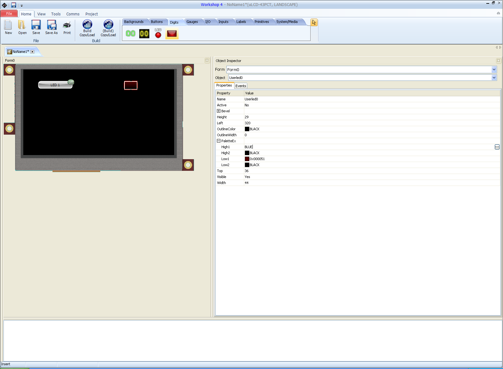
Next click on the Digits tab and select a userLed object and then click on the WYSIWYG screen:
Update the object attributes for the userLed0 object so that it shines blue on activation - you could choose any colour you liked however the LEDS on the Mbed are blue so I thought it should match!
Once you have done all of that which should only take about five minutes we can then get on with the interactive part of the display control. What we want to do is have the display send a message to the host microcontroller when the button state changes from 'off' to 'on'. At the same time we would like to update the userLed0 object on the display from 'off' to 'on' so that the display userLed0 object matches the Mbed LED. So what we are going to do is use the host microcontroller (Mbed) to poll for an event concerning the winButton objects. If the winButton Objects report a message then we know that a button has been pressed and it's state will have changed from Off to On. All we then have to do is get the host micro to send a message to the display telling the virtual LED to change state also and at the same time turn the corresponding actual LED on.
The way this is achieved is to click on the winButton0 object on the WYSIWYG screen and then click on the events tab and then click on the onChanged field. There should be three options - Report Message, Form0 and userLed0Set - choose ReportMessage and click ok.
As there are four LEDS on the Mbed LPC1768 I repeated this process three more times so that there are four button objects and four virtual LED objects. All the winButton objects need to be set up to respond on touch to light the corresponding virtual LED and report a message when their state changes.
This is what you should see now if you are ready for compiling and sending to the display:
Now is the time to save your project and ensure all settings are correct. Save the project as something sensible - I called mine mbedTest but it can be called anything you like. Click on the comms tab and ensure that your display is connected and the COM port for controlling the display is present. Next click on the project tab - Set the appropriate COM port speed for your project. In this case speed is not an issue so I chose 9600 baud:
Now its time to upload our touchscreen layout to the display. Click on the home tab and then click on the 'Build Copy Load' icon. The design will be compiled and uploaded to the display. You will be prompted to copy the files to the microSD also. Once complete remove the microSD card from the reader and put it into the display. You should be presented with your design on the display and when you touch the buttons they should respond appropriately - <BIG GRIN>
That should have taken about ten minutes - it probably took longer to read all of this text, it certainly takes me longer to type it!
Now we are on to coding the firmware for Mbed LPC1768 which I am using as the host microcontroller.
Load up and log into the online compiler for the Mbed in the browser of your choice:
Then start a new program using the blinky LED template, call the program something sensible.
Next import the library files mbed_genie.cpp and mbed_genie.h. These are the library files which tell the mbed how to control the 4D systems touchscreen display. Finally paste in the following code:
#include "mbed.h" #include "mbed_genie.h" DigitalOut led1(LED1); DigitalOut led2(LED2); DigitalOut led3(LED3); DigitalOut led4(LED4); bool winButton0Status = false; //holds the "status" of winButton0 object. bool userLed0Status = false; //hold the "status" of userLed0 object. bool winButton1Status = false; //holds the "status" of winButton1 object. bool userLed1Status = false; //hold the "status" of userLed1 object. bool winButton2Status = false; //holds the "status" of winButton2 object. bool userLed2Status = false; //hold the "status" of userLed2 object. bool winButton3Status = false; //holds the "status" of winButton3 object. bool userLed3Status = false; //hold the "status" of userLed3 object. //Event handler for the 4d Systems display void myGenieEventHandler(void) { genieFrame Event; genieDequeueEvent(&Event); if(Event.reportObject.cmd == GENIE_REPORT_EVENT) { // If the Reported Message was from winbutton0 and userLed0 is off if (Event.reportObject.object == GENIE_OBJ_WINBUTTON) { if ((Event.reportObject.index == 0) && (userLed0Status==false)) { printf("LED1 High \r\n"); wait(0.1); winButton0Status=true; } } // If the Reported Message was from winbutton0 and userLed0 is on if (Event.reportObject.object == GENIE_OBJ_WINBUTTON) { if ((Event.reportObject.index == 0) && (userLed0Status == true)) { printf("LED1 Low \r\n"); wait(0.1); winButton0Status=false; } } // If the Reported Message was from winbutton1 and userLed1 is off if (Event.reportObject.object == GENIE_OBJ_WINBUTTON) { if ((Event.reportObject.index == 1) && (userLed1Status==false)) { printf("LED2 High \r\n"); wait(0.1); winButton1Status=true; } } // If the Reported Message was from winbutton1 and userLed1 is on if (Event.reportObject.object == GENIE_OBJ_WINBUTTON) { if ((Event.reportObject.index == 1) && (userLed1Status == true)) { printf("LED2 Low \r\n"); wait(0.1); winButton1Status=false; } } // If the Reported Message was from winbutton2 and userLed2 is off if (Event.reportObject.object == GENIE_OBJ_WINBUTTON) { if ((Event.reportObject.index == 2) && (userLed2Status==false)) { printf("LED High \r\n"); wait(0.1); winButton2Status=true; } } // If the Reported Message was from winbutton2 and userLed2 is on if (Event.reportObject.object == GENIE_OBJ_WINBUTTON) { if ((Event.reportObject.index == 2) && (userLed2Status == true)) { printf("LED Low \r\n"); wait(0.1); winButton2Status=false; } } // If the Reported Message was from winbutton3 and userLed3 is off if (Event.reportObject.object == GENIE_OBJ_WINBUTTON) { if ((Event.reportObject.index == 3) && (userLed3Status==false)) { printf("LED High \r\n"); wait(0.1); winButton3Status=true; } } // If the Reported Message was from winbutton3 and userLed3 is on if (Event.reportObject.object == GENIE_OBJ_WINBUTTON) { if ((Event.reportObject.index == 3) && (userLed3Status == true)) { printf("LED Low \r\n"); wait(0.1); winButton3Status=false; } } } } int main() { SetupGenie(); genieAttachEventHandler(&myGenieEventHandler); printf("Langsters's mbed Visi-Genie LED demo \r\n"); genieWriteContrast(15); //set screen contrast to full brightness while(1) { //check if winButton0 is High & set LED0 High if (winButton0Status == true) { printf("Button 0 in On State! \r\n"); //send button status message genieWriteObject(GENIE_OBJ_USER_LED, 0x00, 1); // set virtual LED0 High wait(0.1); // wait 100uS led1 = 1; // set actual LED1 High userLed0Status = true; // set userLed0Status High } //check if winButton0 is low & set LED low else if (winButton0Status == false) { printf("Button 0 in Off state! \r\n"); //send button status message genieWriteObject(GENIE_OBJ_USER_LED, 0x00, 0); // set virtual LED0 Low wait(0.1); // wait 100uS led1 = 0; // set actual LED1 Low userLed0Status = false; //set userLed0Status Low } //check if winButton1 is High & set LED High if (winButton1Status == true) { printf("Button 1 in On State! \r\n"); //send button status message genieWriteObject(GENIE_OBJ_USER_LED, 0x01, 1); // set virtual LED0 High wait(0.1); // wait 100uS led2 = 1; // set actual LED2 High userLed1Status = true; // set userLed1Status High } //check if winButton1 is low & set LED low else if (winButton1Status == false) { printf("Button 1 in Off state! \r\n"); //send button status message genieWriteObject(GENIE_OBJ_USER_LED, 0x01, 0); // set virtual LED0 Low wait(0.1); // wait 100uS led2 = 0; // set actual LED1 Low userLed1Status = false; //set userLed1Status Low } //check if winButton2 is High & set LED High if (winButton2Status == true) { printf("Button 2 in On State! \r\n"); //send button status message genieWriteObject(GENIE_OBJ_USER_LED, 0x02, 1); // set virtual LED0 High wait(0.1); // wait 100uS led3 = 1; // set actual LED2 High userLed2Status = true; // set userLed1Status High } //check if winButton2 is low & set LED low else if (winButton2Status == false) { printf("Button 2 in Off state! \r\n"); //send button status message genieWriteObject(GENIE_OBJ_USER_LED, 0x02, 0); // set virtual LED0 Low wait(0.1); // wait 100uS led3 = 0; // set actual LED1 Low userLed2Status = false; //set userLed1Status Low } //check if winButton3 is High & set LED High if (winButton3Status == true) { printf("Button 3 in On State! \r\n"); //send button status message genieWriteObject(GENIE_OBJ_USER_LED, 0x03, 1); // set virtual LED0 High wait(0.1); // wait 100uS led4 = 1; // set actual LED2 High userLed3Status = true; // set userLed1Status High } //check if winButton2 is low & set LED low else if (winButton3Status == false) { printf("Button 3 in Off state! \r\n"); //send button status message genieWriteObject(GENIE_OBJ_USER_LED, 0x03, 0); // set virtual LED0 Low wait(0.1); // wait 100uS led4 = 0; // set actual LED1 Low userLed3Status = false; //set userLed1Status Low } } }