Recently I have been playing with a new microcontroller - NXP's LPC1768 using the mbed development platform.

'mbeds' are incredibly powerful microcontroller development boards handily on a 40 pin dip package which makes it easy for prototyping. Getting into prototyping with ARM microcontrollers is difficult because the devices are usually QFP (read lots of pins, really closely packed together in a surface mounting configuration) - or quad flat packed.....This makes it very hard for the development engineer to quickly prototype circuits. Before protyping begins some sort of development breakout board has to be made which quickly turns into a design of it's own right. There are so many facets and features to microcontrollers these days that prototyping and learning to use the device is a daunting prospect. This is why the arduino development system is so popular....The arduino community have taken the stress out of development by making programming and using the Atmel 328p processor as simple as possible. By then making addon PCBs (shields) available and easy to use the arduino family becomes one of the first development systems I would reach for when designing a microcontroller based electronic circuit
The mbed is a relatively new kid on my block. I have heard about them and given them a cursory glance two years ago. I found the device itself incredibly appealing - mbeds seem to have everything the arduino does and more...the issue was with coding the firmware for the device. The development environment is completely online and this probably puts most professional designers off....control is something inherently closed in electronics design and not sharing is quite common. I am attempting to rectify the situation a little. The other issue is that the mbed is coded entirely in C++. I have dabbled with C++ in the past but I am by no means an expert. To be honest my coding skills lack my electronics considerably! Experienced software developers will revel in coding for the mbed; electronics engineers will struggle but hopefully catch up.
The mbed community website
There are plenty of beginner examples on how to use the mbed on the community website, I'm not going to repeat all of their good work here. Sometimes though I still feel there isn't quite enough detail. If I feel so inclined I might write some tutorials depending on how frustrated I get!
mbed Cookbook
I have recently been tasked with writing the firmware for controlling a touch screen display. I have never played with one of these before and was quite excited at the prospect. The display selected was the uLCD-43 PCT from 4D Systems:
uLCD_43 LCD display

I chose the capacitive touch version as for my application there is going to be a lot of touching and use on the display. Resistive screens tend to get easily scratched and then not work as well, they can be covered but then the responsivity of the display is significantly affected. Capacitive touch screens on the other hand don't lose responsitivity as much when covered and therefore won't be so affected by scratches!
This display was selected because it is controlled via a standard RS232 serial protocol. Only 5 wires required! This should make controlling the display very simple to achieve. I have used touch screen displays in the past that were parallel controlled and 16 wires were required to control the display....16 pins from the microcontroller used to control the display....painful!
There are several versions of touch screen displays available and prices to suit - the smaller the display with less features the cheaper the price!
One trap I found is that if you don't opt to buy one of the development kits 4D systems don't provide a programming cable with the screen. Make sure you buy one or else you will be scuppered in trying to program the display! You will also need a micro-SD card for storing the 'forms' on the display...It would also be beneficial to make sure you have a converter to change the microSD card into a standard SD card or a microSD card reader...I spent forever searching for one!
The development environment for the display provided by 4D Systems is excellent! There are four flavours of environment available.
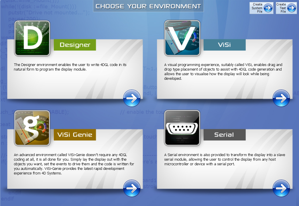
Designer is for the hardcore software programming enthusiast with experience in coding the display using 4D's own development code.
Visi is a drag and drop object oriented programming experience for the controlling the device. It is slightly more simple to use than the Designer option.
Visi-Genie is another even better version of the object oriented drag and drop system. All the designer has to do is drag and drop the pre-coded objects and layout the screen as required. Nothing could be easier and I found this to be the most efficient method of quickly getting the display up and running.
Serial - I haven't really looked into this section much, but according to the information provided it's a method of making the display completely controlled via the serial terminal. I should really investigate further!
There is a very active forum for the use and control of the displays on 4D's website.
If a designer ever got stuck then posting their questions and issues on the forum soon yields some help.
Using Visi-Genie is very similar to a visual development environment and most people who have done any visual programming before will be quite at home.

So to the business of using the screen with the mbed!
I looked at the application notes for using the display on the 4D Systems website and noticed that there were several examples available for use with the arduino and the raspberry Pi. Unfortunately nothing for the mbed. The application notes provided by 4D Systems discuss in great detail how to use the display but connection to the microcontroller is not discussed until the end of the document. It took me a while to find it! There is a specific shield for connecting the display to the arduino and the raspberry Pi and a photograph showing the wired connections to a micro if required. It still wasn't particularly clear to me...so here is how you make connections to any microcontroller with just wires....
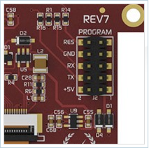
+5V is connected to the 5V positive supply - one will have to be provided for a 3.3V microcontroller
GND is connected to the 0V connection.
RES is connected to a 1k resistor and then to a digital GPIO pin on the microcontroller or not connected.TX is connected to the TX pin of the RS232 Uart pin of choice on the microcontroller.
RX is connected to the RX pin of the RS232 Uart pin of choice on the microcontroller.
For the mbed connections see the following schematic:

I've added a potentiometer as in this tutorial like the arduino tutorial we are going to make a simple touchscreen controlled voltmeter.
I then connected the display to the programming cable and loaded up 4D workshop 4. I selected the Visie-Genie environment and dragged and dropped the following objects onto the display to match the arduino tutorial -
- an angularMeter object
- an LEDdigits object
- two 4Dbuttons object
- three staticText objects

The original arduino tutorial used a rockerSwitch object but I wasn't able to get this working with the mbed....more on this later...
Make sure you set the display's serial communication rate to the same as the one you intend to use with the microcontroller. In my case I selected 115200 as I wanted to see if speed made a difference to the display response.
Set the 4Dbutton objects to Report Message in OnChanged in the events tab. This ensures the display outputs a serial message when the buttons have been pressed.

Once you have the display objects arranged to your satisfaction go ahead and upload the project to the display by clicking on the BuildCopyLoad button. The 'form' will be compiled and loaded onto the display's firmware and then placed on the microSD card. The software will prompt you as required. Once complete remove the SD card and put it in the display. The display will then load up with the form just designed in the development environment - Cool huh!
If you like you can check the display is working by probing the serial port using the serial terminal within 4D systems workshop. When the buttons are pressed a hex message should appear in the serial terminal window.
If however you are like me you will want to connect it to your host micro of choice and use the display as intended - <very big grin>
So remove the USB programming cable and connect the wires up as shown in the schematic diagram previously.
Once you apply power to the mbed the display should load up but not do anything.
You will now need to load up the mbed's online compiler and log in and then you can either develop your own firmware or copy mine...I used a port of the arduino Visi-Genie library helpfully written by Christian B one of the other mbed users:
mbedVoltmeter code
Here is the text version for those that prefer to read through and copy and paste:
/* A port test of the arduino voltmeter example using the
4.3' PCT 4d systems touch screen display.
uses the mbed_genie library ported from the arduino
visie-genie library by Christian B
The display serial TX and RX pins are connected to pin 9
and pin 10 of the mbed
The reset pin is not connected as reset function is not implemented
Pin 15 of the mbed has a potentiometer wiper connected to it
The other connections of the potentiometer are connected to +3.3V
and 0V
For setting up the display in Visie-Genie
The display has an angular meter objecr, a LED digits object, two buttons
and three static text objects.
The program sends digital voltage readings to the LED digits and
angular meter of the display module.
The On and Off button has been set to report on change
The baud rate of the display is set to 115200 baud
*/
#include "mbed.h"
#include "mbed_genie.h"
AnalogIn voltReading(p15); //Potentiometer wiper connected to pin 15
int flag = 0; //holds the "power status" of the voltmeter. flag = 0 means voltmeter is "off", flag = 1 means the voltmeter is "on".
float voltMeter; //holds the digital voltage value to be sent to the angular meter
float voltLED; //holds the digital voltage value to be sent to the LED digits
//Event handler for the 4d Systems display
void myGenieEventHandler(void)
{
genieFrame Event;
genieDequeueEvent(&Event);
//event report from an object
if(Event.reportObject.cmd == GENIE_REPORT_EVENT)
{
/*
for example here we check if we received a message from 4dbuttons objects
the index is the button number, refer to the 4dgenie project to know the index
*/
if (Event.reportObject.object == GENIE_OBJ_4DBUTTON) // If the Reported Message was from a button
{
if (Event.reportObject.index == 0)
{
//printf("Off Button pressed!\n\r");
wait(0.2);
flag=1;
}
if (Event.reportObject.index == 1)
{
//printf("On Button pressed!\n\r");
wait(0.2);
flag=0;
}
}
}
//Cmd from a reported object (happens when an object read is requested)
// if(Event.reportObject.cmd == GENIE_REPORT_OBJ)
// {
// }
}
int main()
{
SetupGenie();
genieAttachEventHandler(&myGenieEventHandler);
printf("Langsters's mbed Visi-Genie Voltmeter demo \n\r");
genieWriteContrast(15); //set screen contrast to full brightness
while(1)
{
if (flag == 1)
{
//printf("Flag status: %d \r\n", flag);
wait (0.1);
voltLED = voltReading;
wait (0.1);
//printf("Volt bit Reading: %f \n\r",voltLED);
voltLED = voltLED * 3.3; //convert float reading to voltage
//printf("voltLED: %f\r\n",voltLED);
voltLED = voltLED * 1000;
genieWriteObject(GENIE_OBJ_LED_DIGITS, 0x00, voltLED); //write to Leddigits0 the value of voltLED
wait (0.1);
voltMeter = voltLED/100;
genieWriteObject(GENIE_OBJ_ANGULAR_METER, 0x00, voltMeter); //write to Angularmeter0 the value of voltMeter
}
else if(flag == 0)
{
//printf("Flag status: %d \r\n", flag);
wait (0.1);
voltLED = 0;
genieWriteObject(GENIE_OBJ_LED_DIGITS, 0x00, 0); //write to Leddigits0 the value of voltLED
wait (0.1);
//voltMeter = voltLED/100;
genieWriteObject(GENIE_OBJ_ANGULAR_METER, 0x00, 0); //write to Angularmeter0 the value of voltMeter
}
}
}
Import the program into your online compiler and then compile and download it. You will then need to copy the associated .bin file onto your mbed. Once complete, press the mbed's reset button and the magic shall begin! If you press the 'On' button the display will show the voltage being applied at the analogue input pin 15 which is connected to the potentiometer wiper and should be somewhere between 0V and 3.3V. If turn the wiper on the pot then the voltage displayed will update accordingly. If you press the 'Off' button all measurement will stop and any changes on the potentiometer will not update the display. Doesn't sound like much but the potential is huge (that and it took me ages to get this working...)
Here is a description of the code and how it works:
#include "mbed.h"
#include "mbed_genie.h"
These two lines tell the online compiler to include the header files mbed.h and mbed_genie.h. These are header files which tell the compiler how to understand the syntax written in the program
AnalogIn voltReading(p15); //Potentiometer wiper connected to pin 15
int flag = 0; //holds the "power status" of the voltmeter. flag = 0 means voltmeter is "off", flag = 1 means the voltmeter is "on".
float voltMeter; //holds the digital voltage value to be sent to the angular meter
float voltLED; //holds the digital voltage value to be sent to the LED digits
The next lines are some variable declarations:
AnalogIn voltReading(p15); tells the compiler that pin 15 on the microcontroller will be using pin 15 to measure an analogue value. In this case it will be measuring the voltage present on the potentiometer wiper pin between 0V and 3.3V
int flag = 0; tells the compiler to assign some memory for storing an 8 bit integer value, refer to this value as flag and give it an initial value of zero. I could have and probably should have used a boolean value here to save memory and it's better practice however I am not a professional coder and this worked!
float voltMeter; tells the compiler to assign some memory for storing a 16bit floating point value or to keep things simple a number with decimals! Refer to this memory location as voltMeter. We will be using this memory location to store the decimal value we are going to display.
float voltLED; As above but in this case we are storing the decimal value to be displayed on the seven segment LED digits.
//Event handler for the 4d Systems display
void myGenieEventHandler(void)
{
genieFrame Event;
genieDequeueEvent(&Event);
//event report from an object
if(Event.reportObject.cmd == GENIE_REPORT_EVENT)
{
/*
for example here we check if we received a message from 4dbuttons objects
the index is the button number, refer to the 4dgenie project to know the index
*/
if (Event.reportObject.object == GENIE_OBJ_4DBUTTON) // If the Reported Message was from a button
{
if (Event.reportObject.index == 0)
{
printf("Off Button pressed!\n\r");
wait(0.2);
flag=1;
}
if (Event.reportObject.index == 1)
{
//printf("On Button pressed!\n\r");
wait(0.2);
flag=0;
}
}
}
The above function is the 'Event Handler' for the display. An event handler is the section of a program for handling interrupts. Basically the microcontroller and display will spend most of it's time showing the pictures of what the designer has provided. When someone touches the display the microcontroller will receive a message from the display interrupting the program flow. This function deals with that 'interruption' by processing it and providing the required response.
In the case above the event handler the following is occurring:
genieFrame Event; Call to the mbed_genie library function that deals with a touch being registered on the display.
genieDequeueEvent(&Event); If the event registered is genuine place it in the queue to be processed as an interrupt.
if(Event.reportObject.cmd == GENIE_REPORT_EVENT)
{
The above line is a conditional check that tells the microcontroller to perform the code below if the result of the check is 'true'. If the result is false the function ends and the microcontroller stops processing this section of code.
if (Event.reportObject.object == GENIE_OBJ_4DBUTTON)
{
Another conditional check asking the microcontroller if a 4Dbutton object was pressed.
if (Event.reportObject.index == 0)
{
printf("Off Button pressed!\n\r");
wait(0.2);
flag=1;
}
Was the button pressed the 4Dbutton0 object - the 'Off' button? If it was then send a message via the serial terminal to advise the user it was (not required but useful for debugging) and then wait 200ms to allow the required processing to occur and then set the flag variable from 0 to 1 to let the microcontroller know the button was pressed.
if (Event.reportObject.index == 1)
{
//printf("On Button pressed!\n\r");
wait(0.2);
flag=0;
}
The above code section is exactly the same as before but for the 'On' button.
int main()
{
SetupGenie();
genieAttachEventHandler(&myGenieEventHandler);
printf("Langsters's mbed Visi-Genie Voltmeter demo \n\r");
genieWriteContrast(15);
The int main() function is the part of the program that tells the microcontroller to process the functions in order from here.
The SetupGenie(); line is a call to the mbed_genie library telling the microcontroller how to setup the display. Tell the microcontroller what size of display is connected, in what orientation and at what speed the serial Uart is set at. In this case I set it to 115200 baud. If this needed to be changed you would need to search through the mbed_genie library for screen.baud (115200) and change it to whichever value you like. You will need to ensure the display firmware is updated to reflect this change. I hope to change this in the library to make it easier to change the screen serial baud rate.
printf("Langsters's mbed Visi-Genie Voltmeter demo \n\r");
The above line sends a message via the serial terminal to inform the viewer which program is running. Not strictly necessary but useful for debugging purposes. It lets the programmer know which section of the code is running.
genieWriteContrast(15);
The above line sets the displays contrast (brightness really). You can set the display from 0 to 15. 15 is full brightness. Useful if you wanted to turn the display off or down to conserve power when not in use.
while(1)
{
if (flag == 1)
{
//printf("Flag status: %d \r\n", flag);
wait (0.1);
voltLED = voltReading;
wait (0.1);
//printf("Volt bit Reading: %f \n\r",voltLED);
voltLED = voltLED * 3.3; //convert float reading to voltage
//printf("voltLED: %f\r\n",voltLED);
voltLED = voltLED * 1000;
genieWriteObject(GENIE_OBJ_LED_DIGITS, 0x00, voltLED); //write to Leddigits0 the value of voltLED
wait (0.1);
voltMeter = voltLED/100;
genieWriteObject(GENIE_OBJ_ANGULAR_METER, 0x00, voltMeter); //write to Angularmeter0 the value of voltMeter
}
else if(flag == 0)
{
//printf("Flag status: %d \r\n", flag);
wait (0.1);
voltLED = 0;
genieWriteObject(GENIE_OBJ_LED_DIGITS, 0x00, 0); //write to Leddigits0 the value of voltLED
wait (0.1);
//voltMeter = voltLED/100;
genieWriteObject(GENIE_OBJ_ANGULAR_METER, 0x00, 0); //write to Angularmeter0 the value of voltMeter
}
}
}
The rest of the code runs in a continuous while loop initiated in the while(1){ section. Every line of code beyond this point will run over and over until power is removed.
The if statement checks if the flag variable has been set and if it is set (the 'On' button has been pressed) then the analogue voltage signal measured on analogue pin 15 is stored and placed in the voltLED memory location. The floating point value is then converted to decimal and formated for a measurement from 0 - 3.3V and then passed to the ledDigit0 display object. The display then shows the result. The same process is then performed to display the voltage measurement on the angularMeter0 display object.
That's it for the code explanation. I hope it's understandable. It took far too long for me to get this working and almost as long to write about it!
Here is a picture of the display and microcontroller in action:

And finally here is the almost ubiquitous youtube video proving I didn't fake getting it working!
Well that's it for now. I am hoping that given time I can help improve the ported 4D systems mbed library as there are still a few functions missing - resetting the display being one thing I found not present. I also didn't manage to get the rocker switch object to work which is why I used two momentary buttons. All in all I think both the mbed microcontrollers and the 4D systems display have great potential and hopefully more people will be able to use them with help from this tutorial.
Take care people - Langster!