One of the most common tasks I need a microcontroller to perform is to log data from instrumentation. The best way I know of currently doing that is to use an SD card. I have done this with an arduino so often I almost can do it without thought. At the moment I am developing some instrumentation with the mbed and need to achieve the same thing - I need a way of logging data measurements. The data will be stored as text files in ASCII. I will probably use comma separated values....It makes it easy to import into a spreadsheet or graphing program of choice.
If you are going to try this you will need the following:
An mbed and mini USB cable
An SD card - partitioned and formatted for use on your operating system of choice
An SD card breakout board - try Adafruit or Sparkfun for all your breakout needs!
Some connection wire
Patience!
So I looked at the mbed documentation on the website and searched for SD card tutorial. A lot of pages appeared but nothing that actually shouted this is how to connect an SD card, here is the circuit diagram and how to connect it up and here is the demonstration code with an explanation of how things work....
https://mbed.org/search/?type=&q=SD+card+tutorial - a lot of pages but nothing definitive
What I actually needed to find was here:
The mbed cookbook is useful but often difficult to navigate - a work in progress.
There is a lot of information on the programming of the mbed - libraries and usage but no pictures on how to connect things up and no schematics. Lets remedy that!

SD cards normally communicate with the host microcontroller via the SPI protocol - Serial Peripheral Interface. The mbed has two SPI ports - pins 5, 6 and 7 - MOSI, MISO and SCK and pins 11,12 and 13 - also MOSI, MISO and SCK. You can use either three pins but they are not interchangeable. In my testing I used 11,12 and 13 because I have already made plans for pins 5 and 7!
Here is a picture of the connections:

I used an SD breakout board so my connections are a little different from the above schematic. I am connecting +5V to Vdd because my breakout board has a logic level converter to convert 5V to 3.3V. The breakout board was designed for use with TTL logic based microcontrollers like the arduino. If you are using just an SD card connector the information in the schematic is correct. Change your connections to suit your breakout board as necessary.
Once I had checked and rechecked my connections! I keep having to do that at the moment - I imported the example code into the online compiler and then uploaded it to my mbed
Here is the the link to the example code again so people can find it easily:
It should compile with no errors. Ensure that you update the code with the relevant information with where you have made the connections. If like me you are using pins 11, 12 and 13 for MOSI, MISO and SCK you need to change the line highlighted to reflect that.
#include "mbed.h"
#include "SDFileSystem.h"
SDFileSystem sd(p11, p12, p13, p8, "sd"); // the pinout on the mbed Cool Components workshop board
int main() {
printf("SD card test!\r\n");
mkdir("/sd/mydir", 0777);
FILE *fp = fopen("/sd/mydir/sdtest.txt", "w");
if(fp == NULL) {
error("Could not open file for write\r\n");
}
fprintf(fp, "Hello fun SD Card World!\r\n");
fclose(fp);
printf("File successfully written and closed!\r\n");
}
I suppose I should try and explain what the code does:
The first line tells the compiler to include the core header file for the mbed and the second include statement tells the compiler to use the header file containing the instructions relating to SD cards.
The third line SDFileSystem sd(p11, p12, p13, p8, "sd"); tells the compiler that the SD card is connected to pins 11, 12 , 13 and pin 8.
NB - Pin 8 is the control line for the SD card it's known as CS or SS depending on which information you read or what is printed on the breakout boards silk screen - mine was SS.
The rest of the code prints a message to the mbed com port, makes a directory on the SD card and then creates a text file called sdtest.txt. If for some reason the file cannot be created or opened an error message is displayed on the serial terminal; the program then finishes. If the file was created and opened successfully a message will be written inside the text file and then the test file is closed. A further message is sent to the serial terminal to document the program's success.
I use a free terminal program called PuTTy for my serial, Telnet or SSH requirements. It is a great piece of software! You can get it from here:
I suggest people try it out - it's useful...
Anyway...back to the cool stuff. Connect up your mbed to your PC and copy the compiled .bin file to your mbed and press the reset button. If all is well the blue power / programming LED will flash and then the program will exit. No other LEDs should be illuminated.
If you load up PuTTy and point it towards your mbed serial terminal with the settings:
COMXX - 9600, n, 8, 1 with no flow control - where XX is the COM port number of your mbed you can view the output:
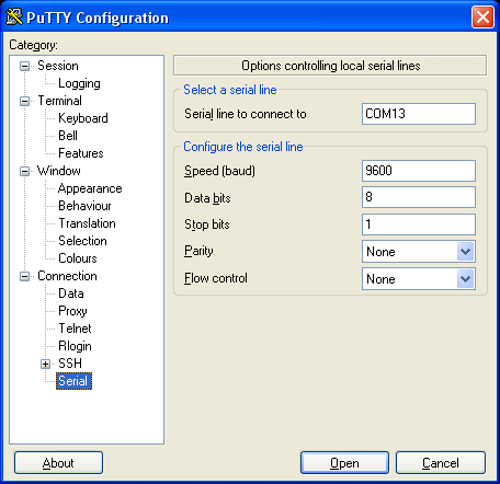
Open the terminal window and view the results...

Actually that was amazing for me...I couldn't get this to work for love nor money at first - I'm losing my touch!
If you remove your SD card and view it in a file explorer there will be a new directory on your SD card called mdir and inside this folder there will be a text file called sdtest.txt. Open it and verify it is all correct.
If things are wrong and they often are...then the four LEDS at the bottom of the mbed will flash from outer to inner and the following messages will be shown in PuTTy:

The flashing LEDS of SD card failure...

If you see this then unfortunately something is wrong either with the wiring, the SD card or your mbed. In my case I was struggling for a long time because I was using the unregulated +5V input to power the SD card. My computer couldn't power both the mbed and the SD card. As soon as I swapped to the regulated +5V everything worked perfectly. If it doesn't work for you, all I can suggest is check check and re-check connections and then ask for help! I didn't but perhaps I should have...I even checked the MOSI, MISO and SCK where occurring using an oscilloscope and a logic analyser. I re-wired at least ten times and checked continuity with a multimeter. It wasn't until I measured the voltages with a digital multimeter that I noticed that there was not enough voltage to power the SD card. If I had been using a breakout board without a logic level converter and wired as shown in the schematic diagram this would have worked first time....No matter - all is working and well now and more information and confidence gained - bonus!
There are so many reasons to want to log data to external memory with microcontrollers - it's the corner stone of instrumentation. I'm going to turn this into a memory stick of sorts so that I just have to connect a USB cable to the mbed (not the programming cable) so that I can browse the SD card data! Simples!
That's all for now people - take care
Langster!
No comments :
Post a Comment