This will hopefully speed up being able to learn to develop custom electronics projects using an FPGA. For me it means I can use the peripherals on the FPGA development board without having to work out how to use them in VHDL which would take me a very long time to learn.
The FPGA Arduino project at the University of Zagreb
Here is what we will need in order to get this working using Windows Operating Systems:
Hardware:
A Mimas V2 FPGA Development Board
A Mini USB Cable
Software:
The Latest build of the Arduino IDE
Numato Firmware Downloader
mimas V2 115200 baud update V.28
XC6SXL9.bin
And all of the associated tools for uploading files to the Mimas V2 Development board which can be found from here:
Mimas V2 Upload Software and USB Driver
Download all of the required files to a suitable hard disk location and unzip any compressed files.
The first thing that is required is to update the firmware on the PIC microcontroller on the Mimas V2 FPGA development board - the firmware update increases the speed of communication between the PIC microcontroller and the FPGA device to 115200 Baud which is what is needed to upload programs from the arduino IDE.
*Warning* There is currently no firmware to return the Mimas V2 PIC Microcontroller to it's original state and the updated firmware is currently beta only - it does have some issues. These are being addressed but at the moment there is currently no way to return the PIC on the Mimas V2 board to its factory settings.
I have not found any issues from doing this upgrade as yet however.
When my version of the Mimas V2 FPGA development arrived as new it did not have some header pins soldered into P3 - So I had to solder some in. This is needed to perform the PIC firmware upgrade:
 |
| Mimas V2 FPGA Development board without Firmware Upgrade Header |
Next you will need to short the pins together to put the PIC Microcontroller into firmware upgrade mode:
Connect up the Mimas V2 FPGA development board to your computer - it's time to update the PIC firmware! When you connect up the FPGA development board windows will install a generic USB driver for the PIC device - this is meant to happen.
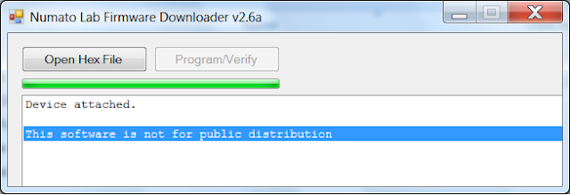
Open the folder where the software has been downloaded and execute up the firmware downloader program, Ignore the standard windows warning message - the program is fine. You should see something similar to the image below:
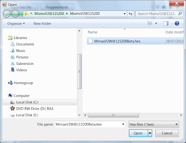
Click on 'Open Hex File' and navigate to where the 115200 baud update file was extracted - it's called MimasV2W@115200Beta.hex:
Click 'Open' to continue and then click on 'Program/Verify':
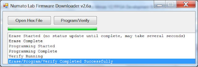
If all went according to plan you should see the above message!
Remove the cable shorting the firmware upgrade pins and load up the programming software MimasV2Config.exe:
Select the COM port associated with your Mimas V2 FPGA Development board - mine was COM 22:
Then click on 'Open File' and navigate to where the XC6SXL9.bin file is located:
Make sure switch SW7 is in the left position closest to the USB connector:
Then click program!
This takes a couple of minutes to complete and once it does you should be presented with the seven segment display activated and the LEDS fading in and out in blocks of four:
 |
| Cool fading LEDS! |
Now load up the Arduino IDE:
Click on the File Menu and select 'Preferences'
Copy and paste the URL below into the 'Additional Boards Manager URLS: Field
http://www.nxlab.fer.hr/fpgarduino/package_f32c_core_index.json
This adds support for various FPGA development boards to the arduino IDE including the Mimas V2:
Click 'OK' to return to the main arduino IDE screen and then click on the tools menu, then 'Board' and select 'Boards Manager':
Scroll down to the bottom of the window where FPGArduino by FER+RIZ+RADIONA is located and select install:
This may take a while...Click close once the installation has completed.
It should now be possible to flash arduino programs to the Mimas V2 FPGA development board!
Click on the 'Tools' menu in the arduino IDE and select Board: There should now be a lot of new boards to select for upload, choose Mimas V2:
Also select the appropriate COM port for your Mimas V2 Board - Mine is COM22...
Then Click on the File Menu and select the 'Blink' Example code, or copy and paste the code below:
/*
Blink
Turns on an LED on for one second, then off for one second, repeatedly.
Most Arduinos have an on-board LED you can control. On the Uno and
Leonardo, it is attached to digital pin 13. If you're unsure what
pin the on-board LED is connected to on your Arduino model, check
the documentation at http://www.arduino.cc
This example code is in the public domain.
modified 8 May 2014
by Scott Fitzgerald
*/
// the setup function runs once when you press reset or power the board
void setup() {
// initialize digital pin 13 as an output.
pinMode(13, OUTPUT);
}
// the loop function runs over and over again forever
void loop() {
digitalWrite(13, HIGH); // turn the LED on (HIGH is the voltage level)
delay(1000); // wait for a second
digitalWrite(13, LOW); // turn the LED off by making the voltage LOW
delay(1000); // wait for a second
}
We need to change the LED pin as PIN 13 corresponds to LED 5 on the Mimas V2 FPGA. The pin configuration or conversion can be calculated from the table in the link below:
FPGA to Arduino Pin Map
From the table we can find that LED D1 on the FPGA development board corresponds to 15 so we need to replace the code with this code:
/*
Blink
Turns on an LED on for one second, then off for one second, repeatedly
on the Numato Labs MIMAS V2 FPGA Development Board
LED 1 on the Mimas V2 FPGA Development board corresponds to pin 15
by Alexander Lang - 28/11/2015
*/
int LED1 = 15; // LED 1 on the mimas V2
// the setup function runs once when you press reset or power the board
void setup() {
// initialize digital pins 8, 11 and 15 as an output.
pinMode(8, OUTPUT);
pinMode(11, OUTPUT);
pinMode(15, OUTPUT);
digitalWrite(8, LOW); // set LED connected to pin 8 low as it is not required
digitalWrite(11, LOW); // set LED connected to pin 11 low as it is not required
}
// the loop function runs over and over again forever
void loop() {
digitalWrite(15, HIGH); // turn the LED on (HIGH is the voltage level)
delay(1000); // wait for a second
digitalWrite(15, LOW); // turn the LED off by making the voltage LOW
delay(1000); // wait for a second
}
Save the code - always a good idea and click upload!
Once that has completed you should be presented with the following: LED D1 on the Mimas V2 Development board is flashing On and Off:
The way this is made possible is that the arduino firmware is constantly sent to the FPGA via the PIC Microcontroller. If you move SW7 to the left position again you will return the FPGA to it's previous state with the cool LED Fade...You will need to do this every time you would like to upload some different arduino code to the Mimas V2 FPGA.
Do you remember the classic TV series Knight Rider? If so you will remember with fondness the LED pattern used at the front of the bonnet to show that the car was 'talking' - Just for fun lets turn on all the LEDS in the classic knight rider sweep!
Here is the code, copy and paste this into the arduino IDE:
/*
Sweep the LEDS like they did on Knight Rider
on the Numato Labs MIMAS V2 FPGA Development Board
by Alexander Lang - 28/11/2015
*/
int D1 = 15; // LED 1 on the mimas V2
int D2 = 14; // LED 1 on the mimas V2
int D3 = 13; // LED 1 on the mimas V2
int D4 = 12; // LED 1 on the mimas V2
int D5 = 11; // LED 1 on the mimas V2
int D6 = 10; // LED 1 on the mimas V2
int D7 = 9; // LED 1 on the mimas V2
int D8 = 8; // LED 1 on the mimas V2
int timer = 50; //delay for 100 ms
void setup(){
pinMode(D1, OUTPUT);
pinMode(D2, OUTPUT);
pinMode(D3, OUTPUT);
pinMode(D4, OUTPUT);
pinMode(D5, OUTPUT);
pinMode(D6, OUTPUT);
pinMode(D7, OUTPUT);
pinMode(D8, OUTPUT);
digitalWrite(8, LOW); // set LED connected to pin 8 LOW to begin
digitalWrite(11, LOW); // set LED connected to pin 11 LOW to begin
}
void loop() {
digitalWrite(D1, HIGH);
delay(timer);
digitalWrite(D1, LOW);
digitalWrite(D2, HIGH);
delay(timer);
digitalWrite(D2, LOW);
digitalWrite(D3, HIGH);
delay(timer);
digitalWrite(D3, LOW);
digitalWrite(D4, HIGH);
delay(timer);
digitalWrite(D4, LOW);
digitalWrite(D5, HIGH);
delay(timer);
digitalWrite(D5, LOW);
digitalWrite(D6, HIGH);
delay(timer);
digitalWrite(D6, LOW);
digitalWrite(D7, HIGH);
delay(timer);
digitalWrite(D7, LOW);
digitalWrite(D8, HIGH);
delay(timer);
digitalWrite(D8, LOW);
digitalWrite(D7, HIGH);
delay(timer);
digitalWrite(D7, LOW);
digitalWrite(D6, HIGH);
delay(timer);
digitalWrite(D6, LOW);
digitalWrite(D5, HIGH);
delay(timer);
digitalWrite(D5, LOW);
digitalWrite(D4, HIGH);
delay(timer);
digitalWrite(D4, LOW);
digitalWrite(D3, HIGH);
delay(timer);
digitalWrite(D3, LOW);
digitalWrite(D2, HIGH);
delay(timer);
digitalWrite(D2, LOW);
digitalWrite(D1, HIGH);
delay(timer);
digitalWrite(D1, LOW);
}
Save the file and then manipulate SW7 from right to left and then back to right to 'set' the Mimas ready to receive the arduino code and then click upload!
You should see something like the video below when the code has been successfully loaded onto the FPGA:
There are some examples available to further test the arduino compatibility, Try them, I couldn't get serial communications to work but the boulder example looked quite cool if you have VGA monitor spare you can load up the classic arcade game:
 |
| Classic Arcade games on the Mimas V2 |


This comment has been removed by the author.
ReplyDeletecould you please say how to do this same process in windows 10 because i used the same procedure in windows 7 it works but not working in windows 10
ReplyDeleteArun,
DeleteI have not tried to this in a very long time. It sounds unusual that it 'works' for windows 7 but not windows 10. Which part does not 'work'? If you have managed to update the microcontroller on the board to accept serial communcations at 115200 baud it should work irrespective of which operating system is being used.
I will try and get this working when I get home and see if I have the same problem.
Cheers
Alex
Thank you for the help.It works on win 10 by adding some dll files
ReplyDeleteHello good sir. Thank god for your tutorial as it helped me flash this bad boy with some arduino goodness which I otherwise would have fully failed to do. The original website from the guys that made the stuff was a little lacking and has some dead links.
ReplyDeleteQuestion for ya - I found a post on a forum you made (I think it was you) which had a link to a tool showing the PIN assignments for switches, leds, the 7 segment, all that good stuff. I was wondering though, do you happen to have somewhere the pin assignments for P6, P7, P8, P9 IO banks? Or the P5 dipswitch? I found what they are when normally used with Xilinx and VDHL and such. Assignments like "U5" "R7" etc. I don't know how to translate that to the arduino pin assignments. Any help?
appears to be 32 to 63 from what I found in a random source file.. if this is right, then nevermind! Now i need to figure out how to change stupid VREF cuz whatever it's at now is too low. I think 0.55v or something. I'm trying to get the 3.3v on the pins :(
DeleteI apologize, seems these wire jumpers im using dont work great with the board. it's apparently utilizing LVCMOS25? 2.5V it seems.
DeleteI think this needs a bootloader, since the settings go back to default every time power is removed.
ReplyDelete