Showing posts with label Pressure Sensor. Show all posts

Friday, 10 March 2017

Multifunctional Medical Training Device

A blog reader has asked me to help them design and build a medical training device.  The reader is a medical doctor specialising in Pulmonary treatment and training - In the course of their work they measure how much air flow goes in and out of a person's lungs and how that is affected.  The device to be built needs to measure the following things to a reasonable accuracy:
  • Air pressure
  • Air flow
  • Thoracic and Abdominal movement (Using EMG - electromyography)
It would be nice if the device was as accurate as possible, battery powered and wireless as much as possible to make it easy to use and less invasive to the patient.

I'm going to help them by designing something that does all of the above using the arduino microcontroller as the main processor.  The circuit will also have a bluetooth module or ESP8266 wifi module to provide serial communications to an external PC or mobile phone application to display the results.

In order to start the design work we need to assess the instrumentation requirements.  To that end we need to investigate how much air flow and pressure is present in a normal setting and the extreme needed to be measured. From that it should be possible to estimate the requirements for the sensing elements of the device.


The above websites discuss how a medical practitioner performs the above measurements and the associated results expected.  Unhelpfully for an engineer designing equipment the measurement units provided are not clear.  Apparently the results of the testing are quoted as the volume of air inhaled and exhaled in Litres / minute.  So we need a sensor that can measure flow in litres / second or milli-litres per second.  There is no mention of air pressure in those measurements and having had some feedback from the blog reader the pressure measurement is for measuring the pressure from an external ventilator device. The flow probably relates to how much air is ingested into the lungs and the exhaled volume should be slightly lower which indicates how much oxygen was received by the lungs and how much carbon dioxide was produced as part of the operation, We could of course provide sensors for those gases as well. The air pressure would relate to how much a person's diaphragm and chest movement affect the volume of air was inhaled and exhaled and finally this can be corroborated with the EMG measurement.  I don't have much experience with EMG - I made an ECG heart rate monitor many years ago but have mostly forgotten all about it.  EMG is a similar measurement technique.


I am not a pulmonary medical expert so this is conjecture at the moment.  With further discussion I suspect the brief can be expanded upon as required.  For now I will discuss how I intend to implement the device.

The test subject will wear a mask covering the nose and mouth and with tubes attached to the mask which allow the user to breath in and out normally.  Those tubes will be connected to the pressure and flow sensor which in turn will send electronic signal data to an analogue to digital converter which will then pass digital information to a microcontroller (the arduino).  The data received can then be sent out serially and also via Bluetooth or WiFi to an external computer for further processing and graphical display. 

I have no budget for this project so I'm free to choose as I please (I'm paying, so whilst I can choose whatever I like, I'm not a rich person so I'm going to try and cut cost where I can).

The sensors I'm going to use are:

MPS20N0040D-D - I've used it before and I have a pre-designed breakout board (Massive Grin)

MPXV7002DP - I've not used this one before but its easily available with a breakout board and is fairly in-expensive.  I bought mine from ebay for £20
3 Terminal ECG pads and wires - available from Ebay in China at £5.99 for the wires and £5.91 for the pads.

All of these items are available from any good auction website if one looks hard enough:

Ebay - Air Flow Pressure Senor

Ebay - ECG Leads

Ebay - ECG Pads

I'm not sure how physically large the circuit will end up being so I'm not going to specify and enclosure at the moment - Once I have an idea of size I will choose something suitable or design an enclosure that can be 3D printed.

I am currently waiting for parts to arrive from China, once they do I will develop and test the first part of the circuit.

That's all for now - Take care always

Langster!

Thursday, 9 June 2016

Designing a pressure sensor using Velostat


In the previous post I designed a circuit which was supposed to read in when pressure was applied to a custom sensor made from velostat.

The first post on the Piano conversion

I made a sensor out of some single sided FR4 printed circuit board material, some foam tape, two pieces of wire, a small 1 cm x 1 cm piece of velostat and some sticky tape!

Custom Pressure Sensor using Velostat
This is just a prototype and may not be my final version of the sensor. I wanted to see how well velostat worked and how it would behave. It seems to work really well!

I found from measurements with my multimeter that when the pressure sensor is not touched the resistance across the wires is 30 kΩ. When pressure is applied it drops to 1 kΩ. That should be more than good enough for the purposes of detecting a key-press!

The constructed pressure sensor
Next the PCB designed in the previous post was etched, drilled and populated. It etched well and I populated it with the designed components:

The Underside of the PCB 
The topside of the PCB with components

I then wrote some quick test code for the arduino because I'm leaning towards using an arduino for the microcontroller:

/*
Pressure Sensor test Code
For Electronic Piano
(c) A. Lang 2016
 
*/

// These constants won't change.  They're used to give names
// to the pins used:
const int analogInPin = A0;  // Pressure Sensor connected to A0

int sensorValue = 0;        // value read from the pressure sensor via the amplifier stage
float outputValue = 0;      // value output to the Serial port

void setup() {
  // initialize serial communications at 9600 bps:
  Serial.begin(9600); 
}

void loop() {
  // read the analog in value:
  sensorValue = analogRead(analogInPin);            

  // print the results to the serial monitor:
  Serial.print("sensor = " );                       
  Serial.print(sensorValue); 
  Serial.println();
       
  // wait 10 milliseconds before the next loop
  // for the analog-to-digital converter to settle
  // after the last reading:
  delay(10);                     
}
The code is very similar to code I had written before - what is it with me and pressure sensors at the moment! I then uploaded the code to the arduino and tested it - It didn't work as planned - I may have been a little disappointed at this point....

I then thought about my circuit and looked at the schematic:

The original Key Press schematic

I realised I had made a mistake. I didn't account for how the velostat would behave in terms of it's resistance. I thought it would have a resistance of around 1 kΩ and vary....it doesn't it's resistance is 30 kΩ and varies down from that when pressure is applied. Because of this I need to tweak my circuit from behaving as a two stage buffer to a simple analogue comparator and buffer. Luckily it won't be too hard to change things!

Here is the new circuit:

Add caption
The Key Press Schematic Version 2 

The new circuits works in a similar fashion as the previous one. The velostat pressure sensor makes up a voltage divider. The output of the voltage divider is connected to an analogue comparator made with the first op-amp in an LM358 dual op-amp IC. The negative input has a 2.75 V reference set by the 8.2 kΩ resistor and the 10 kΩ resistor. The output of the 1st op-amp is then connected to a buffer amplifier with a gain of two and then the output is connected to a FET and an LED. The output will be sent to the ADC of the micro-controller which will probably be an Arduino.

To test the circuit I removed a 10 kΩ resistor and then added a 7.5 kΩ resistor (because I couldn't find an 8.2 kΩ resistor). Here is a photo of the modification:


Here is the modified PCB layout although I probably won't etch this board again. I'm going to re-design it to use surface mount components and be a smaller form factor. It would be nice if each board fit snugly under each piano key.

The New Key Press Layout
I then connected the circuit back up to the arduino and pressed the sensor! It worked. The LED lit up - although I wish I had used a brighter LED...but SUCCESS!! So sweet...


Here is a graph I made from the serial monitor results. It looks very similar to the simulated oscilloscope trace from the first post!
The results from the serial monitor
So now we have a valid method of reading key presses we need to scale things up - and shrink a few things down. I will redesign the key press PCB layout to use surface mount components to take up as little room as possible. Then we need to look at multiplexing all of the signals together...and for that I'm going to use the 74HC4076 integrated circuit breakout board.

That's all for now people - take care!

Monday, 30 May 2016

Calibrating a MPS20N0040D-D Pressure Sensor

It has recently become apparent that readers of the pressure sensor posts on my blog need a way of calibrating the MPS20N0040D-D pressure sensors.

Here is the original post on pressure sensors:

http://langster1980.blogspot.co.uk/2014/11/how-to-use-pressure-sensor-with.html

This is not too difficult but you will need a few items:
  • An air pump - a bicycle pump will do.
  • An air pressure gauge - something with a human readable scale, preferably calibrated...
  • An MPS20N0040D-D pressure sensor and the difference amplifier set to the gain required for the circuit in mind - Hint I sell breakout boards here - Buy a pressure sensor breakout board
  • An arduino uno or other suitable microcontroller development board.
Once you have everything ready connect up the pressure sensor, analogue electronics to the arduino - I used the analogue zero pin, use whichever analogue pin required but make of note of it as the code needs to match the circuit.

Connection Diagram


Once you have everything connected as above upload the code below into the arduino:

/*
Pressure Sensor test Code
 */

const int analogInPin = A0;  // Sensor connected to A0

int sensorValue = 0;        // value read from the pressure sensor via the amplifier stage
float outputValue = 0;      // value output to the Serial port

void setup() {
  // initialize serial communications at 9600 bps:
  Serial.begin(9600); 
}

void loop() {
  // read the analog in value:
  sensorValue = analogRead(analogInPin);            
  
  // print the results to the serial monitor:
  Serial.print("sensor = " );                       
  Serial.print(sensorValue);  
  
  Serial.println();
       
  delay(1000);                     
}

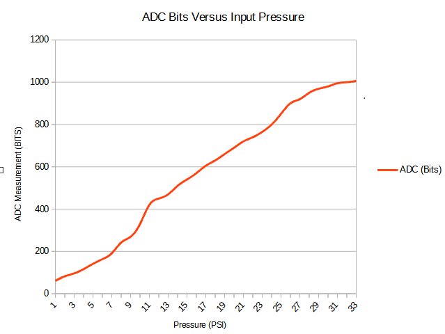
Now open the serial monitor in the arduino IDE.  Observe the bit value received when no pressure is applied to the sensor.  This is the zero value.  Now introduce air pressure to the sensor using the pump.  When the external gauge reads 1 psi record the value of bits received.  Repeat this process until you have reached 32 psi or when 1023 bits has been recorded.  Create a table of results, mine looked like this:


Input pressure
ADC
ADC voltage
(PSI)
(Bits)
(volts)
0
61
0.283295132
1
82
0.4001820137
2
96
0.4740954967
3
116
0.5620723363
4
141
0.6742689746
5
163
0.7817888563
6
191
0.9386412512
7
242
1.183020528
8
269
1.329648094
9
329
1.632903226
10
420
2.052785924
11
450
2.19941349
12
470
2.2971652
13
510
2.492668622
14
540
2.639296188
15
570
2.785923754
16
605
2.956989247
17
630
3.079178886
18
660
3.225806452
19
690
3.372434018
20
720
3.519061584
21
740
3.616813294
22
765
3.739002933
23
800
3.910068426
24
850
4.154447703
25
900
4.398826979
26
920
4.49657869
27
950
4.643206256
28
969
4.736070381
29
980
4.789833822
30
995
4.863147605
31
1000
4.887585533
32
1006
4.916911046

Now that the results have been obtained we can plot a graph which shows how the number of bits received relate to the amount of pressure present.  We could work this out from the table but it's much easier to visualise this using a graph:


We can use the information from the graph and the table to display the pressure measured in psi. There are several methods to achieve this such as a lookup table which will interpolate the results.  I have decided to use a map function as the results obtained a quite linear (a straight line was achieved). 

Arduino Map Function

Enter the highest value obtained and the lowest value obtained and apply it to the scale needed (in this case PSI) and the function will do the rest for us:

outputValue = map(sensorValue, 60, 1006, 0, 32);  

Here is the full code in case people need it:

/*
Pressure Sensor test Code
 */

const int analogInPin = A0;  // Sensor connected to A0

int sensorValue = 0;        // value read from the pressure sensor via the amplifier stage
float outputValue = 0;      // value output to the Serial port

void setup() {
  // initialize serial communications at 9600 bps:
  Serial.begin(9600); 
}

void loop() {
  // read the analog in value:
  sensorValue = analogRead(analogInPin);            
  
  // print the results to the serial monitor:
  Serial.print("sensor = " );                       
  Serial.print(sensorValue); 
  
  outputValue = map(sensorValue, 60, 1006, 0, 32);  // convert the raw bit value 

  Serial.print("sensor = " );                       
  Serial.print(outputValue); 
  
  Serial.println();
       
  delay(1000);                     
}

Hope this helps people make more use of the MPS20N0040D-D pressure sensor.
 

That is all for now - take care people!