Saturday, 22 March 2014

How to make a Printed Circuit Board!

Its been a while since I posted!  One of the blog subscribers has asked me to write a step by step guide on how to make a printed circuit board.  There are many guides available online already and this is my version. I hope people find it useful.

There are several methods of making a permanent electronic circuit.  Engineers and makers alike use many different methods.  The most popular by far is making a printed circuit board or PCB.  The board material or substrate itself is a glass reinforced plastic sheet material is known as FR4.

FR4 wikipedia entry

Its a a glass reinforced plastic sheet designed specifically for the purpose of supporting electronic components.  The FR4 material is cladded or coated in copper on either one or both sides to allow the electrical circuit to be made.

PCB wikipedia entry

For hobbyists and makers there are two distinct methods of manufacturing a PCB.  The design or layout for the electronic circuit is drawn as a series of lines and shapes in a suitable piece of design software, printed on a transfer medium such as glossy paper or acetate sheet.  This design is then transferred to the copper clad FR4 sheet either by exposure to ultra-violet light or by using heat to transfer the design.

Before this can begin the following materials will need to be obtained:

1x piece of copper clad FR4 PCB material
It needs to be slightly larger than the total area of the design you intend to make.  If you are looking to use the UV exposure method ensure you buy UV resist coated FR4 PCB material.


Buy FR4 Single Sided PCB from EBAY - not UV resist coated and therefore much cheaper!

Buy UV coated single sided PCB from EBAY - UV coated and therefore more expensive

Some glossy paper or acetate sheet for transferring the design

120 GSM glossy paper - matt one side, smooth on the other (for the toner transfer method)

Inkjet compatible acetate sheet - (for the UV exposure method)

A clothes iron or a plastic film laminator - (toner transfer method)
As a clothes iron can be obtained just about anywhere I'm not going to provide a link!


A UV light source - (UV exposure method)
These aren't cheap so I made my own with a load of UV LEDS and a small power supply but a daylight bulb or a professional light box can also be used.

Professional UV exposure box - EBAY, very expensive!!

I made a UV light source similar to the one detailed here using LEDS, resistors and some veroboard and a 12V power supply.  The guide is also very informative:

How to make a UV Light Box - Cheaper, but you will need at least 30 UV LEDS, 30 75 Ohm Resistors, a 12V power supply, solder, wire, tools and a black plastic box to put the light source in.  You don't want to be able to see the UV light.  It damages your eyes!


UV BlackLight Bulb - Cheaper and quicker still - use a Blacklight to expose the design on to the PCB.


Some development solution - (UV exposure method)

Universal development granules - You will need to add tap water to the granules in order to make up the solution.  Follow the instructions provided.  You will need a plastic bottle to store the solution for later.


Another supplier of Development Solution

A plastic tray for the development solution and to hold the PCB material


An etch tank or plastic tray to hold and store the etching fluid
I made a special tank for this with a PCB holding net and an air pump to agitate the PCB etchant.


Some PCB Etching Fluid - (Both methods)

I use ferric Chloride which can be bought in powder or crystal form and then tap water is added to make up the PCB Etching Fluid


Finally some latex or rubber gloves, some eye protection goggles a lab coat or work clothes and some plastic tweezers - These should all be available on EBAY or locally in a hardware store.


Once you have obtained all of these things the process can begin...Exciting times!

The first thing you will need after you have got all of the required items is the PCB layout you wish to make a printed circuit board for.  There are several software packages that electronics engineers and makers use for this purpose.  I use EagleCad.  It's an open source program developed by cadsoft which can be downloaded here:


Next you will need to draw the schematic diagram and then design the PCB layout.  I won't go through the nuances of using the program here as it takes a long time and there is much to discuss.  If a tutorial on using eagle is needed please let me know in the comments section.

I have posted many images of schematics in various previous posts.  Below is an image for an arduino shield I have designed.  It's an audio amplifier using a very popular LM386 amplifier.


The parts list for this circuit:

1x LM386 audio amplifier
1x 10uF Electrolytic Capacitor
1x 220uF Electrolytic Capacitor
1x 47nF Ceramic or mica film Capacitor
1x 10 Ohm Resistor
1x 10k Potentiometer
100x Male pin Headers for connections
1x piece of single sided FR4 printed circuit board - dimensions to follow

Once I had drawn the schematic I laid out the electrical connections to make a single sided PCB:  The screen shot below shows the design and the components arranged and all of the tracks connected.  To make the PCB we will need to print out this design with just the blue tracks and green pads displayed.


So in order to do that I need to turn off the 'layers' in eagle that are not required:


At this point we are ready to start the preparations for making our PCB.  I will do the process for the UV transfer method first.

UV Transfer Method of making a PCB:

1.  With the PCB layout complete as above print out the layout with only Pads, tracks and overall dimensions of PCB displayed.  Load the printer with printer friendly clear acetate sheet.  Ensure printing is not scaled (1:1) or mirrored and is in black and white.  I like to make a PDF of my layout as I find it prints with a slightly darker hue.  I also use a laser printer as I have found these work better.

2.  Next its time to take the print out of the design on acetate and cut it to size.  After it's printed make sure you know which way up the design is.  You don't want to mirror the design!

3.  Next cut out the pre sensitised PCB to size.  Leave a little extra just in case at the edges.  Do not peel off the protective film and expose the PCB yet!  Once it's cut to size take the acetate print out of the layout (cut that to size) and place it on top of the PCB, Now peel off the protective film and place the acetate on the pre-sensitised copper layer - ensure you have the design the right way up as you don't want to mirror the layout!  Hold the layout in place with box clips or masking tape.  Make sure you don't obscure any of the layout!


4.  Expose the PCB and combined acetate layout to UV light for at least ten minutes.  Some experimentation at this stage may be necessary.  Sometimes it takes a longer or shorter time.  There is no empirically correct exact time.  Once complete remove the UV light source and then take the acetate off the copper clad PCB material.  Again take care not to mark the sensitive copper side with fingerprints.  I have heard that it is possible to expose UV sensitised PCBS using sunlight.  I don't know how long the boards are exposed for or how effective this is - I just know it should be possible as there is UV light present in sunlight...

5.  Make up some of the sodium hydroxide development solution following the instructions given.  Don't mix up more than you need as I find the solution does not keep well.  Place the exposed PCB in the developing tray (clean plastic tray or box).  Gently agitate the solution over the PCB until you start to see the layout appear as a brown or green coloured design.


As soon as the design is fully exposed remove the PCB from the development solution and place it in some clean tap water.  It is important to stop the development solution over exposing and clearing all of the tracks off.  If you over expose you will have to start again with a new piece of pre-sensitised PCB....practice makes perfect and I have had mixed results.  It is why I prefer to use the toner transfer method of making PCBS.

6.  Once the PCB design has been properly transferred to the PCB it's time to etch the uncoloured copper away using the ferric chloride or whichever etchant fluid you are using.  Place the PCB in the etch tank with the design facing up or into a plastic box filled with etchant or suitable etchant container.  Make sure it is not metallic as ferric chloride or any etchant for that matter eats through most metals!


7.  Gently rock and agitate the etchant for about ten minutes.  Using plastic tweezers or taking care roll the etch tank to one side so that you can see the design.  See if the unexposed copper has been removed.  If it hasn't continue agitating the solution until it has been completely removed.


8.  Remove the PCB from the etching fluid and clean it using tap water.  Be careful not to get etching fluid onto anything metallic.  You should be left with a very clean and detailed etched printed circuit board!

9.  Drill out any holes as required - my designs are nearly all through hole so I have lots of drilling to do!

10.  Finally populate and test your PCB - hopefully it will work first time - Good luck!

Toner Transfer method of making a PCB:

1.  Load a laser printer (it has to be a laser printer) with 120 GSM glossy paper.  Make sure the smooth side is the side that is presented to the toner ink. Print out the PCB layout with only the tracks, pads and dimensions present.  Be sure the printout is mirrored before you begin.


2.  Once you have the printout on glossy paper its time to get hold of the blank copper clad PCB material. Cut it to size and clean the copper using a polishing block or pencil eraser.  The copper area needs to be cleaned to remove any excess dirt or grease.  At this point I wear plastic or latex gloves to prevent finger prints.  You could also use wire wool.


3.  Heat up a clothes iron to as hot as possible - make sure there is no water in the iron (if its a steam iron). Place the printed PCB layout toner side down onto the cleaned copper side of the PCB.  If needed secure the printout in place using masking tape or box clips.  I use an old piece of wood to press down on when I iron on the design.  The heat causes the toner to transfer from the paper onto the PCB; About 5 minutes of ironing should see the design properly transferred.  Practice makes perfect!


4.  Once you are happy the design has been transferred turn off the iron and place the PCB into a bucket of cold tap water.  Be aware the PCB is probably quite hot so use suitable heat protective gloves or tongs! You can just leave the PCB to cool but I'm impatient!  Next soak the paper off the PCB exposing just the ink and the copper.  I like to use an old toothbrush to clean off the excess paper.

5.  Once complete inspect your transfer.  You should be able to read any text present and there should be no broken tracks.  If there are broken tracks you can touch them up using an acid resistant marker pen like the permanent markers used for writing on acetate sheets.  If the design didn't transfer well at all you can clean off the toner and repeat the process from step 3 onwards.  Again practice makes perfect and this is why I prefer the toner transfer method.  I can rectify mistakes early on.


6.  Now it's time to etch the PCB using the etchant of choice.  Place the PCB in the etch tank with the design facing up or into a plastic box filled with etchant or suitable etchant container.  Make sure it is not metallic as ferric chloride or any etchant for that matter eats through most metals!


8.  Gently rock and agitate the etchant for about ten minutes.  Using plastic tweezers or taking care roll the etch tank to one side so that you can see the design.  See if the uncovered copper has been removed.  If it hasn't continue agitating the solution until it has been completely removed.

9.  Once all of the uncovered copper has been removed take the PCB out of the etch tank and clean the PCB in tap water.  Once all of the ferric chloride has been removed, clean off the black toner using wire wool or something suitably abrasive.  You should be left with something similar to the picture below:


10.  After that it's time to drill any holes required using a suitable pillar drill and drill sizes before populating your PCB with components and soldering it up.  Hopefully if it was designed properly it will perform the function you require!

Well that's about it.  I hope this guide is useful to people.  Please comment or contact me if you need more help or information.  That's about it for now - take care always - Langster!

Wednesday, 29 January 2014

mbed controlling a 4D Systems uLCD-43PCT and four LEDS

Hi, I have been playing with the Mbed Microcontroller and the 4D Systems Capacitive 4.3' touchscreen.  In order to familiarise myself with the nuances of the system and because I was asked by a reader of the blog if something was possible....So here we go - this is an example of how to use the 4D systems touch screen to turn four leds on and off.  To keep things simple I am using the four LEDS already present on the Mbed LPC1768 however any LEDS connected to any pins could be used.

So here is the schematic - I'm a great believer in schematics!


I then loaded up 4D Systems graphical development environment - Workshop 4 ready to develop the touchscreen display:


Next to start a completely new project I clicked on the appropriate 'Create a new Project Button'  When presented with the following screen I scrolled down to the appropriate display type - in my case a 4.3 inch capacitive touch screen.  I chose the landscape non reversed orientation because I'm lazy and haven't really decided how I am going to mount the display, all possible permutations of orienting the display are catered for.


Click next when you are ready to continue and the following choose your development environment screen is displayed - Lets choose Visi-Genie because its the most simple and quick to use; I can't stress how good and easy this development environment is!!


The next screen displayed is the workshop for graphical development environment.  On the left side of the screen is what is referred to in the manual as the 'WYSIWYG' of the touch screen.  What you see is what you get - quite literally.  On the right side of the screen are all of the attributes available for the graphical screen objects that you as the designer may place on the WYSIWYG screen:


As I'm doing an example of lighting some external LEDS with some buttons lets add some button objects:

Click on the 'Buttons' tab and then on the fancy buttons icon ( icon with a spanner on an orange background) :-


Next click on the WYSIWYG touch screen to place a 'fancy button' - it will automatically be called winButton0:


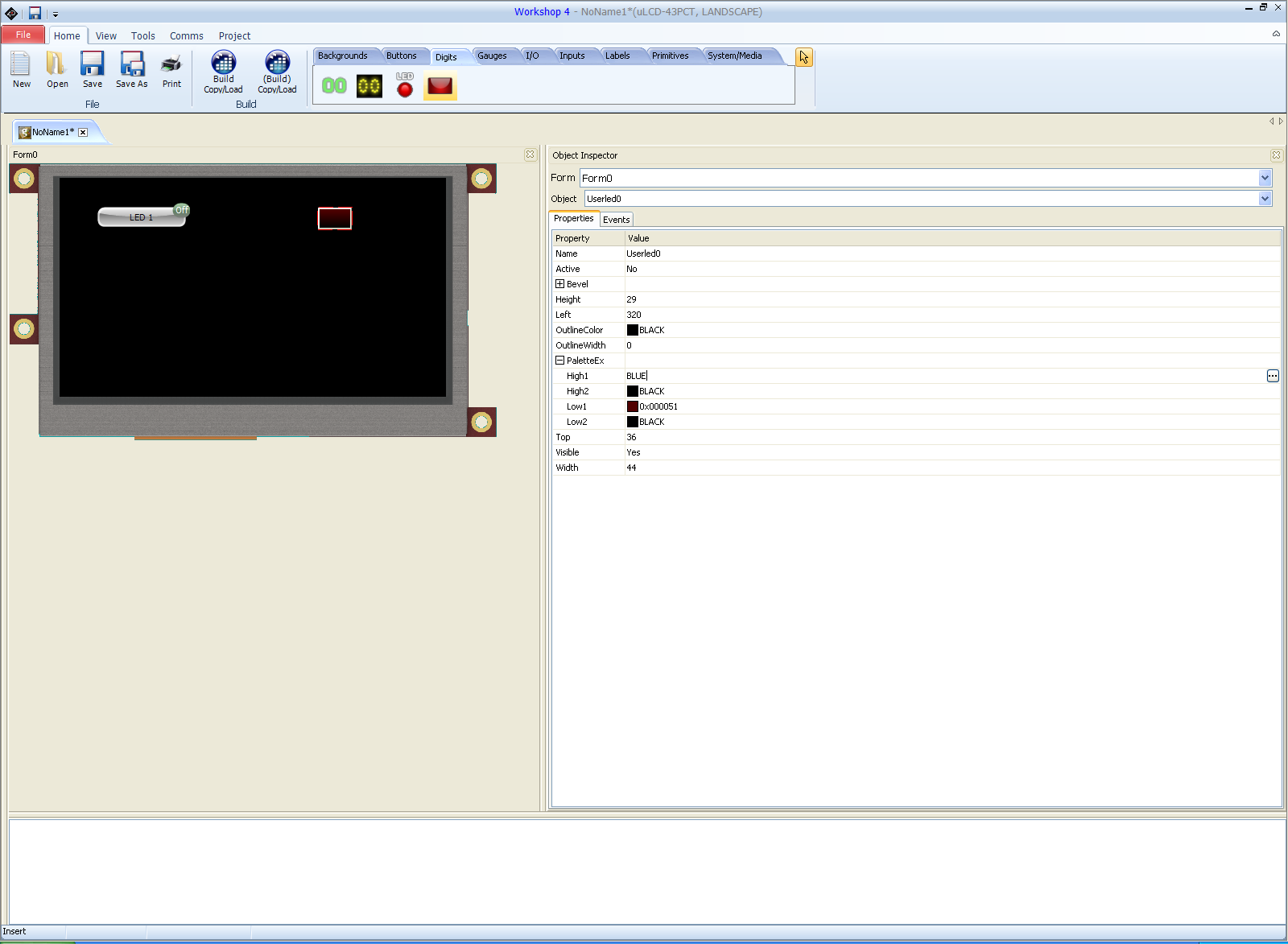
On the right side of the screen the 'object inspector' will show all of the pertinent attributes for the winButton0 object.  Lets modify the button so that it is no longer a momentary button and give it a better label than winButton0 and lets also have the display show when the button has been actuated 'On' and 'Off':

Make sure the properties tab is selected

Click on the caption field and change it from winButton0 to something more appropriate - I chose LED 1

Click on the momentary field and change it from 'Yes' to 'No'

Expand the 'StatusWhenOff' field and change the BGcolor to Green and the caption to 'Off' or whatever you like

Expand the 'StatusWhenOn' field and change the BGcolor to Red and the caption to 'On' or whatever you like


You might notice that the WYSIWYG display updates the winButton0 object with your changes...and displays the correct caption and shows the button in 'Off' state.

Next click on the Digits tab and select a userLed object and then click on the WYSIWYG screen:


Update the object attributes for the userLed0 object so that it shines blue on activation - you could choose any colour you liked however the LEDS on the Mbed are blue so I thought it should match!

Once you have done all of that which should only take about five minutes we can then get on with the interactive part of the display control.  What we want to do is have the display send a message to the host microcontroller when the button state changes from 'off' to 'on'.  At the same time we would like to update the userLed0 object on the display from 'off' to 'on' so that the display userLed0 object matches the Mbed LED.  So what we are going to do is use the host microcontroller (Mbed) to poll for an event concerning the winButton objects.  If the winButton Objects report a message then we know that a button has been pressed and it's state will have changed from Off to On.  All we then have to do is get the host micro to send a message to the display telling the virtual LED to change state also and at the same time turn the corresponding actual LED on.

The way this is achieved is to click on the winButton0 object on the WYSIWYG screen and then click on the events tab and then click on the onChanged field.  There should be three options - Report Message, Form0 and userLed0Set - choose ReportMessage and click ok.


As there are four LEDS on the Mbed LPC1768 I repeated this process three more times so that there are four button objects and four virtual LED objects.  All the winButton objects need to be set up to respond on touch to light the corresponding virtual LED and report a message when their state changes.

This is what you should see now if you are ready for compiling and sending to the display:


Now is the time to save your project and ensure all settings are correct.  Save the project as something sensible - I called mine mbedTest but it can be called anything you like.  Click on the comms tab and ensure that your display is connected and the COM port for controlling the display is present. Next click on the project tab - Set the appropriate COM port speed for your project.  In this case speed is not an issue so I chose 9600 baud:


Now its time to upload our touchscreen layout to the display.  Click on the home tab and then click on the 'Build Copy Load' icon.  The design will be compiled and uploaded to the display.  You will be prompted to copy the files to the microSD also.  Once complete remove the microSD card from the reader and put it into the display.  You should be presented with your design on the display and when you touch the buttons they should respond appropriately  - <BIG GRIN>

That should have taken about ten minutes - it probably took longer to read all of this text, it certainly takes me longer to type it!

Now we are on to coding the firmware for Mbed LPC1768 which I am using as the host microcontroller.
Load up and log into the online compiler for the Mbed  in the browser of your choice:

Then start a new program using the blinky LED template, call the program something sensible.


Next import the library files mbed_genie.cpp and mbed_genie.h.  These are the library files which tell the mbed how to control the 4D systems touchscreen display.  Finally paste in the following code:

#include "mbed.h"
#include "mbed_genie.h"

DigitalOut led1(LED1);
DigitalOut led2(LED2);
DigitalOut led3(LED3);
DigitalOut led4(LED4);

bool winButton0Status = false; //holds the "status" of winButton0 object.
bool userLed0Status = false;   //hold the "status" of userLed0 object.

bool winButton1Status = false; //holds the "status" of winButton1 object.
bool userLed1Status = false;   //hold the "status" of userLed1 object.

bool winButton2Status = false; //holds the "status" of winButton2 object.
bool userLed2Status = false;   //hold the "status" of userLed2 object.

bool winButton3Status = false; //holds the "status" of winButton3 object.
bool userLed3Status = false;   //hold the "status" of userLed3 object.


//Event handler for the 4d Systems display
void myGenieEventHandler(void)
{
    genieFrame Event;
    genieDequeueEvent(&Event);

    if(Event.reportObject.cmd == GENIE_REPORT_EVENT) {

        // If the Reported Message was from winbutton0 and userLed0 is off

        if (Event.reportObject.object == GENIE_OBJ_WINBUTTON) {
            if ((Event.reportObject.index == 0) && (userLed0Status==false)) {
                printf("LED1 High \r\n");
                wait(0.1);
                winButton0Status=true;
            }
        }

        // If the Reported Message was from winbutton0 and userLed0 is on

        if (Event.reportObject.object == GENIE_OBJ_WINBUTTON) {
            if ((Event.reportObject.index == 0) && (userLed0Status == true)) {
                printf("LED1 Low \r\n");
                wait(0.1);
                winButton0Status=false;
            }
        }

        // If the Reported Message was from winbutton1 and userLed1 is off

        if (Event.reportObject.object == GENIE_OBJ_WINBUTTON) {
            if ((Event.reportObject.index == 1) && (userLed1Status==false)) {
                printf("LED2 High \r\n");
                wait(0.1);
                winButton1Status=true;
            }
        }

        // If the Reported Message was from winbutton1 and userLed1 is on

        if (Event.reportObject.object == GENIE_OBJ_WINBUTTON) {
            if ((Event.reportObject.index == 1) && (userLed1Status == true)) {
                printf("LED2 Low \r\n");
                wait(0.1);
                winButton1Status=false;
            }
        }

        // If the Reported Message was from winbutton2 and userLed2 is off

        if (Event.reportObject.object == GENIE_OBJ_WINBUTTON) {              
            if ((Event.reportObject.index == 2) && (userLed2Status==false)) {
                printf("LED High \r\n");
                wait(0.1);
                winButton2Status=true;
            }
        }

        // If the Reported Message was from winbutton2 and userLed2 is on

        if (Event.reportObject.object == GENIE_OBJ_WINBUTTON) {              
            if ((Event.reportObject.index == 2) && (userLed2Status == true)) {
                printf("LED Low \r\n");
                wait(0.1);
                winButton2Status=false;
            }
        }
        
        // If the Reported Message was from winbutton3 and userLed3 is off

        if (Event.reportObject.object == GENIE_OBJ_WINBUTTON) {              
            if ((Event.reportObject.index == 3) && (userLed3Status==false)) {
                printf("LED High \r\n");
                wait(0.1);
                winButton3Status=true;
            }
        }

        // If the Reported Message was from winbutton3 and userLed3 is on

        if (Event.reportObject.object == GENIE_OBJ_WINBUTTON) {              
            if ((Event.reportObject.index == 3) && (userLed3Status == true)) {
                printf("LED Low \r\n");
                wait(0.1);
                winButton3Status=false;
            }
        }
    }
}


int main()
{

    SetupGenie();

    genieAttachEventHandler(&myGenieEventHandler);

    printf("Langsters's mbed Visi-Genie LED demo \r\n");

    genieWriteContrast(15); //set screen contrast to full brightness

    while(1) {

        //check if winButton0 is High & set LED0 High 

        if (winButton0Status == true) {
            printf("Button 0 in On State! \r\n");     //send button status message
            genieWriteObject(GENIE_OBJ_USER_LED, 0x00, 1); // set virtual LED0 High     
            wait(0.1); // wait 100uS
            led1 = 1; // set actual LED1 High
            userLed0Status = true; // set userLed0Status High

        }

        //check if winButton0 is low & set LED low 

        else if (winButton0Status == false) {
            printf("Button 0 in Off state! \r\n");    //send button status message
            genieWriteObject(GENIE_OBJ_USER_LED, 0x00, 0); // set virtual LED0 Low      
            wait(0.1); // wait 100uS
            led1 = 0; // set actual LED1 Low
            userLed0Status = false; //set userLed0Status Low

        }
        
        //check if winButton1 is High & set LED High 
        
        if (winButton1Status == true) {
            printf("Button 1 in On State! \r\n");     //send button status message
            genieWriteObject(GENIE_OBJ_USER_LED, 0x01, 1); // set virtual LED0 High     
            wait(0.1); // wait 100uS
            led2 = 1; // set actual LED2 High
            userLed1Status = true; // set userLed1Status High

        }

        //check if winButton1 is low & set LED low 

        else if (winButton1Status == false) {
            printf("Button 1 in Off state! \r\n");    //send button status message
            genieWriteObject(GENIE_OBJ_USER_LED, 0x01, 0); // set virtual LED0 Low      
            wait(0.1); // wait 100uS
            led2 = 0; // set actual LED1 Low
            userLed1Status = false; //set userLed1Status Low

        }
        
        //check if winButton2 is High & set LED High 
        
        if (winButton2Status == true) {
            printf("Button 2 in On State! \r\n");     //send button status message
            genieWriteObject(GENIE_OBJ_USER_LED, 0x02, 1); // set virtual LED0 High     
            wait(0.1); // wait 100uS
            led3 = 1; // set actual LED2 High
            userLed2Status = true; // set userLed1Status High

        }

        //check if winButton2 is low & set LED low 

        else if (winButton2Status == false) {
            printf("Button 2 in Off state! \r\n");    //send button status message
            genieWriteObject(GENIE_OBJ_USER_LED, 0x02, 0); // set virtual LED0 Low      
            wait(0.1); // wait 100uS
            led3 = 0; // set actual LED1 Low
            userLed2Status = false; //set userLed1Status Low

        }
        
        //check if winButton3 is High & set LED High 
        
        if (winButton3Status == true) {
            printf("Button 3 in On State! \r\n");     //send button status message
            genieWriteObject(GENIE_OBJ_USER_LED, 0x03, 1); // set virtual LED0 High     
            wait(0.1); // wait 100uS
            led4 = 1; // set actual LED2 High
            userLed3Status = true; // set userLed1Status High

        }

        //check if winButton2 is low & set LED low 

        else if (winButton3Status == false) {
            printf("Button 3 in Off state! \r\n");    //send button status message
            genieWriteObject(GENIE_OBJ_USER_LED, 0x03, 0); // set virtual LED0 Low      
            wait(0.1); // wait 100uS
            led4 = 0; // set actual LED1 Low
            userLed3Status = false; //set userLed1Status Low

        }        
        

    }

}

------------------------------------------------------------------------------------------------------------

You can also import the code as an example from the Mbed cookbook here:

mbed 4D LED Test

The code is fairly simple to understand and is well documented so I'm not going to discuss it more here.

Here is a video showing the screen working - Enjoy.


That's all for now - Langster!


Tuesday, 14 January 2014

mbed SD Card tutorial

I have been playing with the mbed microcontroller again.  I'm really liking this particular microcontroller development platform!  The potential is huge for what can be achieved with this thing.  The only thing I continually struggle with is the documentation.  Whilst the mbed website is good there are still issues that cause the inexperienced to become frustrated...myself included!

One of the most common tasks I need a microcontroller to perform is to log data from instrumentation.  The best way I know of currently doing that is to use an SD card.  I have done this with an arduino so often I almost can do it without thought.  At the moment I am developing some instrumentation with the mbed and need to achieve the same thing - I need a way of logging data measurements.  The data will be stored as text files in ASCII.  I will probably use comma separated values....It makes it easy to import into a spreadsheet or graphing program of choice.

If you are going to try this you will need the following:

An mbed and mini USB cable
An SD card - partitioned and formatted for use on your operating system of choice
An SD card breakout board - try Adafruit or Sparkfun for all your breakout needs!
Some connection wire
Patience!


So I looked at the mbed documentation on the website and searched for SD card tutorial.  A lot of pages appeared but nothing that actually shouted this is how to connect an SD card, here is the circuit diagram and how to connect it up and here is the demonstration code with an explanation of how things work....

https://mbed.org/search/?type=&q=SD+card+tutorial - a lot of pages but nothing definitive

What I actually needed to find was here:


The mbed cookbook is useful but often difficult to navigate - a work in progress.

There is a lot of information on the programming of the mbed - libraries and usage but no pictures on how to connect things up and no schematics.  Lets remedy that!


SD cards normally communicate with the host microcontroller via the SPI protocol - Serial Peripheral Interface.  The mbed has two SPI ports - pins 5, 6 and 7 - MOSI, MISO and SCK and pins 11,12 and 13 - also MOSI, MISO and SCK.  You can use either three pins but they are not interchangeable.  In my testing I used 11,12 and 13 because I have already made plans for pins 5 and 7!

Here is a picture of the connections:


I used an SD breakout board so my connections are a little different from the above schematic.  I am connecting +5V to Vdd because my breakout board has a logic level converter to convert 5V to 3.3V.  The breakout board was designed for use with TTL logic based microcontrollers like the arduino.  If you are using just an SD card connector the information in the schematic is correct.  Change your connections to suit your breakout board as necessary.

Once I had checked and rechecked my connections!  I keep having to do that at the moment - I imported the example code into the online compiler and then uploaded it to my mbed

Here is the the link to the example code again so people can find it easily:


It should compile with no errors.  Ensure that you update the code with the relevant information with where you have made the connections.  If like me you are using pins 11, 12 and 13 for MOSI, MISO and SCK you need to change the line highlighted to reflect that.

#include "mbed.h"
#include "SDFileSystem.h"

SDFileSystem sd(p11, p12, p13, p8, "sd"); // the pinout on the mbed Cool Components workshop board

int main() {
    printf("SD card test!\r\n");   

    mkdir("/sd/mydir", 0777);
    
    FILE *fp = fopen("/sd/mydir/sdtest.txt", "w");
    if(fp == NULL) {
        error("Could not open file for write\r\n");
    }
    fprintf(fp, "Hello fun SD Card World!\r\n");
    fclose(fp); 

    printf("File successfully written and closed!\r\n");
}

I suppose I should try and explain what the code does:

The first line tells the compiler to include the core header file for the mbed and the second include statement tells the compiler to use the header file containing the instructions relating to SD cards.

The third line SDFileSystem sd(p11, p12, p13, p8, "sd");  tells the compiler that the SD card is connected to pins 11, 12 , 13 and pin 8. 

NB - Pin 8 is the control line for the SD card it's known as CS or SS depending on which information you read or what is printed on the breakout boards silk screen - mine was SS.

The rest of the code prints a message to the mbed com port, makes a directory on the SD card and then creates a text file called sdtest.txt.  If for some reason the file cannot be created or opened an error message is displayed on the serial terminal; the program then finishes.  If the file was created and opened successfully a message will be written inside the text file and then the test file is closed. A further message is sent to the serial terminal to document the program's success.

I use a free terminal program called PuTTy for my serial, Telnet or SSH requirements.  It is a great piece of software!  You can get it from here:


I suggest people try it out - it's useful...

Anyway...back to the cool stuff.  Connect up your mbed to your PC and copy the compiled .bin file to your mbed and press the reset button.  If all is well the blue power / programming LED will flash and then the program will exit.  No other LEDs should be illuminated.  

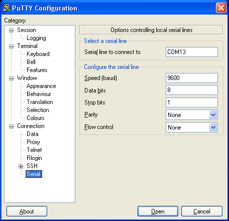
If you load up PuTTy and point it towards your mbed serial terminal with the settings:

COMXX - 9600, n, 8, 1 with no flow control - where XX is the COM port number of your mbed you can view the output:


Open the terminal window and view the results...


Actually that was amazing for me...I couldn't get this to work for love nor money at first - I'm losing my touch!

If you remove your SD card and view it in a file explorer there will be a new directory on your SD card called mdir and inside this folder there will be a text file called sdtest.txt.  Open it and verify it is all correct.

If things are wrong and they often are...then the four LEDS at the bottom of the mbed will flash from outer to inner and the following messages will be shown in PuTTy:


The flashing LEDS of SD card failure...


If you see this then unfortunately something is wrong either with the wiring, the SD card or your mbed.  In my case I was struggling for a long time because I was using the unregulated +5V input to power the SD card.  My computer couldn't power both the mbed and the SD card.  As soon as I swapped to the regulated +5V everything worked perfectly.  If it doesn't work for you, all I can suggest is check check and re-check connections and then ask for help!  I didn't but perhaps I should have...I even checked the MOSI, MISO and SCK where occurring using an oscilloscope and a logic analyser.  I re-wired at least ten times and checked continuity with a multimeter.  It wasn't until I measured the voltages with a digital multimeter that I noticed that there was not enough voltage to power the SD card.  If I had been using a breakout board without a logic level converter and wired as shown in the schematic diagram this would have worked first time....No matter - all is working and well now and more information and confidence gained - bonus!

There are so many reasons to want to log data to external memory with microcontrollers - it's the corner stone of instrumentation.  I'm going to turn this into a memory stick of sorts so that I just have to connect a USB cable to the mbed (not the programming cable) so that I can browse the SD card data!  Simples!

That's all for now people - take care

Langster!