So the picture above shows the PCB top layer with components and dimensions. We can use this to design an enclosure for the project. For quickness and because its so easy I have decided to make a laser cut box out of wood! Laser cutting is the simplest and quickest way I have found to make unit enclosures. As this is essentially a display piece I've decided to use laser plywood. I'll stain and varnish it to give it a good aesthetic appeal. This isn't really my thing in honesty. I normally just like things to work I don't care how they look but the customer (she who must be obeyed!) has more stringent criterion...
To design the box ready for laser cutting I used Inkscape an open source graphics package which is awesome -
Inkscape
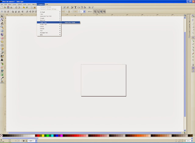
After installing and setting up the program and checking it was working I then added an extension and this is where designing boxes becomes so simple and efficient - tabbed box maker!
Tabbed Box Maker Extension for Inkscape
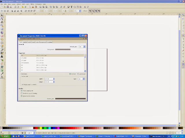
Once installed I then set my page size and limits to A4, Landscape orientation and the grid dimensions to be in millimetres...because I am a shameless Brit and use SI units and paper sizes and I have a working knowledge of those units and dimensions. If you want to use Imperial measurements that is fine too!
Next it's time to start the tabbed box maker extension:
A window will appear with some options about the box we are going to design.
So now is the time to make some decisions about the box....We know roughly what our internal dimensions need to be...As they will be the same as the PCB. We also need to allow some space for the solenioid to be comfortable and we need to choose how deep we want the box to be....too shallow and it will sound poor when 'knocking' but too tall is a waste of material. In the end it's up to the designer. Here is what I chose:
I like to work with the internal dimensions as I want to be sure whatever I'm going to put inside the box or enclosure is going to fit. I have made mistakes before when designing enclosures by using the internal dimensions for external dimensions...All I can say is be careful and check things before cutting material or getting something made. It can get expensive!
For the length dimension I chose 145mm...it was a guess really, I looked at the PCB and my solenoid and from the dimensions of those I surmised 145mm would be ok. For the width I chose 100mm as it's slightly larger than the PCB and should make it fit without being too tight. From the PCB dimensions we have 94mm width. So if we choose to make the internal box width 100mm we have a 3mm margin between the PCB and the box walls:
100mm - 94mm = 6mm
6mm / 2 = 3mm margin
For the height I made a guess and chose 75mm. There was no real science involved I just chose a number!
The tab width was set to 5mm because I like having 5mm tabs. If you choose a different value here be sure you know what you are doing. More tabs makes the box more secure as you are providing more surface area for the glue to act upon but it can make the box very difficult to put together.
The material thickness I set to 5mm because that's the thickness of my laser plywood which I bought from an art shop in Manchester called Fred Aldous:
They sell all manner of art materials and supplies and also provide laser cutting services.
I didn't change the kerf parameter (kerf = the amount of material the cutting action removes) and the clearance parameter I also left unchanged.
I chose a 3 piece layout style because it makes it fit a page of A4 well. I chose the space between parts to be 2mm because I didn't want to waste material.
When it comes time to laser cut the box we will need to cut it twice to ensure we get all of the parts we need.
Click apply when ready and this is what the extension generates:
Next I decided to get clever...In eagle on the PCB layout section I turned all layers off on my PCB view apart from dimensions and holes.
I then exported this image as a PDF. I then imported this image into Inkscape on a new layer. This will allow me to set the laser cutter to drill out the holes for the PCB mounts perfectly aligning them! I then drew some circles over the top of the hole positions and then deleted the PCB image as it isn't needed. Finally I grouped the holes with the bottom tabbed box shape so they wouldn't move.
I love getting laser cutters to do all the work for me! Time is precious...
Next we need to add a hole in the side of the box for the DC power Jack. This is a bit more complicated as I don't have a 3 dimensional representation of the box. I could model this in Google Sketchup but it isn't necessary...I can guess where the hole needs to be from the dimensions of the DC jack and the PCB layout.
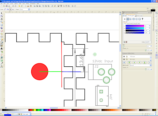
I added all of the components and a dimension from the edge of the PCB to the centre of the DC jack to help...technically not needed. If we draw a line from the DC jack centre across to the left we can position the centre of the hole. Next we draw another like from the edge of the tab section so that we know where the base of the side begins....I know this is difficult to understand hopefully the picture will make it clear:
The red line shows the base of the side when the box will be put together and the blue line shows where the centre of the DC jack plug will be.
What we need to do now is calculate of big a hole we need and where it needs to be positioned. The size of the hole really depends on the size of the plug used. I am using a 12Vdc adapter that I found in my junk pile. I grabbed it and measured the diameter of the DC plug roughly using a ruler. If you are making your own adapter then use the mechanical information from the datasheets! It measured roughly 10mm and to be honest they will all be about this size. So...Hole diameter is 10mm.
Next we need to calculate the height the DC jack will be from the base of the side. This is where things get tricky and some luck is needed. I used a standard DC jack socket on the PCB...I didn't even look for something specific as it's a standard part. Here is a datasheet:
PCB Mount DC Jack Socket
From the mechanical information I know that it is 11mm tall and the height to the centre of the jack socket is 6.5mm tall. The PCB thickness is 1.6mm and I intend using PCB stand offs 5mm tall. Therefore if we add the pertinent dimensions together we can calculate where the centre of the hole needs to be:
6.5mm + 1.6mm + 5mm = 13.1mm
So the centre of our 10mm hole needs to be 13.1mm from the base of the side. No problem! Lets add a 10mm hole to our side.
Lets draw another line that is exactly 13.1mm long and overlay it on top of the blue line and beginning at the red line. Then lets add a 10mm diameter circle.
We can then delete the lines and group the hole. Now we have a correctly positioned hole and are ready to cut the wood!
I saved the file with a different name as I will have to cut the material for six parts. One with holes and one without. I decided to add some images to my file to make the box look a little more interesting. The first box I designed was a little plain and boring.
If required I can provide the inkscape files so people can make their own box.
Here is a very quick video of the laser cutter in action:
Now it's finally time to put the box together. The tabs make it very easy and all that was required was some PVA wood glue and some patience. Once the glue set I put the PCB in the box, I was in a rush so I didn't use stand offs and the solenoid was secured with blu tac! I will improve my version but I would recommend that people use stand offs and hot glue to secure their solenoid and PCB.
Here is the box!
In order to properly finish up this product I suppose I should provide a bill of materials and some rough costs. So...here goes:
| Part | Value | Device | Cost (£) |
| C1 | 22pF | Ceramic capacitor | 0.04 |
| C2 | 22pF | Ceramic capacitor | 0.04 |
| C3 | 0.1uF | Electrolytic Capacitor | 0.036 |
| C4 | 10uF | Electrolytic Capacitor | 0.052 |
| C5 | 10uF | Electrolytic Capacitor | 0.052 |
| C6 | 100nF | Ceramic capacitor | 0.028 |
| C7 | 100nF | Ceramic capacitor | 0.028 |
| D1 | 1N4001 | Axial rectifier | 0.056 |
| IC1 | LM7805 | T0220 package | 0.31 |
| J1 | Programming Header | 6x 0.1' pitch header pins | 0.7 |
| J2 | 12Vdc power jack | 3.5mm dc power jack | 1.15 |
| JP1 | 6 pin Header | 6x 0.1' pitch header pins | 0.7 |
| JP2 | 5 pin Header | 5x 0.1' pitch header pins | 0.7 |
| JP3 | 5mm Screw Terminal | 5mm screw terminal phoenix connector | 0.42 |
| JP4 | 5mm Screw terminal | 5mm screw terminal phoenix connector | 0.42 |
| KK1 | Heatsink | T0220 Heatsink | 1.09 |
| LED1 | 5mm Red LED | 5mm Red LED | 0.069 |
| Q1 | IRF630 | MOSFET-N CHANNEL | 0.57 |
| R1 | 10k | 1/4W axial resistor | 0.018 |
| R2 | 220R | 1/4W axial resistor | 0.016 |
| R3 | 1k | 1/4W axial resistor | 0.017 |
| R4 | 100k | 1/4W axial resistor | 0.017 |
| R5 | 1M | 1/4W axial resistor | 0.017 |
| S1 | Microswitch | momentary tactile switch | 0.057 |
| SP1 | Piezo Buzzer | Piezo Buzzer | 0.37 |
| U1 | ATMEGA328P | ATMEGA328P -DIP package | 2.01 |
| Y1 | 16MHz | 16MHz crystal (through hole) | 0.35 |
| DS1307 | Real time Clock Module | DS1307 RTC module | 7.99 |
| PCB | Circuit Board | Printed Circuit Board | 2.55 |
| Total | 19.873 |
Some of the components have to be ordered in multiples from Farnell Electronics so there would be some items left over and it would not be necessary to order three lots of header pins, one 36 row of pins would be enough. The heatsink is also a little unnecessary for this circuit as the MosFET doesn't get hot without one. The 12Vdc 5mm screw terminal for the power input could be removed also. If we now recalculate that brings the cost of making this device (not including enclosure) to £16.96
If we add on two sheets of laser plywood (£2.00) and time on the laser cutter (£1.00 for ten minutes) and it took about twenty minutes to cut the enclosure out:
That bring our total costs back up to £21.96!
Not too bad...It would have been nice to get the costs down below £20 and if I searched around for different suppliers I might be able to get some components more cheaply. If I was in the business of manufacturing products I would be searching everywhere for a better deal. I would also redesign the PCB to be smaller, use surface mount components and have the enclosures made in large numbers. This would reduce costs considerably.
Anyway enough of the boring stuff. I had great fun making this project and I probably will get some printed circuit boards professionally made by Seeed Studios. Their fusion service is too good to miss!
Well that's it for now. Enjoy people and have fun - Langster!


