Saturday 28 November 2015

Arduino Soft Processor on the Mimas V2 FPGA Development Board (Windows)

A very interesting development has occurred courtesy of some very clever and helpful people at the Radiona Makerspace in Croatia who have been in collaboration with Faculty of Electrical Engineering at the University of Zagreb.  They have implemented a soft processor version of the arduino bootloader making it possible to use the Arduino IDE and libraries to control various FPGA development boards and of particular interest to me: The Mimas V2 from Numato Labs * Really Big Grin *

This will hopefully speed up being able to learn to develop custom electronics projects using an FPGA.  For me it means I can use the peripherals on the FPGA development board without having to work out how to use them in VHDL which would take me a very long time to learn.

The FPGA Arduino project at the University of Zagreb

Here is what we will need in order to get this working using Windows Operating Systems:

Hardware:

A Mimas V2 FPGA Development Board
A Mini USB Cable

Software:

The Latest build of the Arduino IDE
Numato Firmware Downloader
mimas V2 115200 baud update V.28
XC6SXL9.bin

And all of the associated tools for uploading files to the Mimas V2 Development board which can be found from here:

Mimas V2 Upload Software and USB Driver

Download all of the required files to a suitable hard disk location and unzip any compressed files.

The first thing that is required is to update the firmware on the PIC microcontroller on the Mimas V2 FPGA development board - the firmware update increases the speed of communication between the PIC microcontroller and the FPGA device to 115200 Baud which is what is needed to upload programs from the arduino IDE.

*Warning* There is currently no firmware to return the Mimas V2 PIC Microcontroller to it's original state and the updated firmware is currently beta only - it does have some issues.  These are being addressed but at the moment there is currently no way to return the PIC on the Mimas V2 board to its factory settings.

I have not found any issues from doing this upgrade as yet however.

When my version of the Mimas V2 FPGA development arrived as new it did not have some header pins soldered into P3 - So I had to solder some in.  This is needed to perform the PIC firmware upgrade:

Mimas V2 FPGA Development board without Firmware Upgrade Header
Here is my board with the header pins soldered in:


Next you will need to short the pins together to put the PIC Microcontroller into firmware upgrade mode:


Connect up the Mimas V2 FPGA development board to your computer - it's time to update the PIC firmware!  When you connect up the FPGA development board windows will install a generic USB driver for the PIC device - this is meant to happen.

Open the folder where the software has been downloaded and execute up the firmware downloader program, Ignore the standard windows warning message - the program is fine.  You should see something similar to the image below:


Click on 'Open Hex File' and navigate to where the 115200 baud update file was extracted - it's called MimasV2W@115200Beta.hex:


Click 'Open' to continue and then click on 'Program/Verify':


If all went according to plan you should see the above message!

Remove the cable shorting the firmware upgrade pins and load up the programming software MimasV2Config.exe:


Select the COM port associated with your Mimas V2 FPGA Development board - mine was COM 22:


Then click on 'Open File' and navigate to where the XC6SXL9.bin file is located:


Make sure switch SW7 is in the left position closest to the USB connector:


Then click program!


This takes a couple of minutes to complete and once it does you should be presented with the seven segment display activated and the LEDS fading in and out in blocks of four:

Cool fading LEDS!
Close down MimasV2Config.exe and move the switch SW7 to the right position away from the USB connector as shown in the above picture.

Now load up the Arduino IDE:


Click on the File Menu and select 'Preferences'


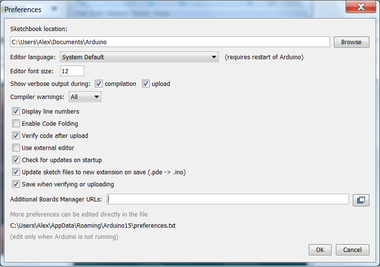
Copy and paste the URL below into the 'Additional Boards Manager URLS: Field

http://www.nxlab.fer.hr/fpgarduino/package_f32c_core_index.json

This adds support for various FPGA development boards to the arduino IDE including the Mimas V2:


Click 'OK' to return to the main arduino IDE screen and then click on the tools menu, then 'Board' and select 'Boards Manager':


Scroll down to the bottom of the window where FPGArduino by FER+RIZ+RADIONA is located and select install:


This may take a while...Click close once the installation has completed.

It should now be possible to flash arduino programs to the Mimas V2 FPGA development board!

Click on the 'Tools' menu in the arduino IDE and select Board:  There should now be a lot of new boards to select for upload, choose Mimas V2:


Also select the appropriate COM port for your Mimas V2 Board - Mine is COM22...

Then Click on the File Menu and select the 'Blink' Example code, or copy and paste the code below:

/*
  Blink
  Turns on an LED on for one second, then off for one second, repeatedly.

  Most Arduinos have an on-board LED you can control. On the Uno and
  Leonardo, it is attached to digital pin 13. If you're unsure what
  pin the on-board LED is connected to on your Arduino model, check
  the documentation at http://www.arduino.cc

  This example code is in the public domain.

  modified 8 May 2014
  by Scott Fitzgerald
 */


// the setup function runs once when you press reset or power the board
void setup() {
  // initialize digital pin 13 as an output.
  pinMode(13, OUTPUT);
}

// the loop function runs over and over again forever
void loop() {
  digitalWrite(13, HIGH);   // turn the LED on (HIGH is the voltage level)
  delay(1000);              // wait for a second
  digitalWrite(13, LOW);    // turn the LED off by making the voltage LOW
  delay(1000);              // wait for a second
}

We need to change the LED pin as PIN 13 corresponds to LED 5 on the Mimas V2 FPGA.  The pin configuration or conversion can be calculated from the table in the link below:

FPGA to Arduino Pin Map

From the table we can find that LED D1 on the FPGA development board corresponds to 15 so we need to replace the code with this code:

/*
  Blink
  Turns on an LED on for one second, then off for one second, repeatedly
  on the Numato Labs MIMAS V2 FPGA Development Board

  LED 1 on the Mimas V2 FPGA Development board corresponds to pin 15
  
  by Alexander Lang - 28/11/2015

 */

int LED1 = 15; // LED 1 on the mimas V2 

// the setup function runs once when you press reset or power the board
void setup() {
  // initialize digital pins 8, 11 and 15 as an output.
  pinMode(8, OUTPUT);
  pinMode(11, OUTPUT);
  pinMode(15, OUTPUT);
  
  digitalWrite(8, LOW); // set LED connected to pin 8 low as it is not required
  digitalWrite(11, LOW); // set LED connected to pin 11 low as it is not required
}

// the loop function runs over and over again forever
void loop() {
  digitalWrite(15, HIGH);   // turn the LED on (HIGH is the voltage level)
  delay(1000);              // wait for a second
  digitalWrite(15, LOW);    // turn the LED off by making the voltage LOW
  delay(1000);              // wait for a second
}

Save the code - always a good idea and click upload!


Once that has completed you should be presented with the following: LED D1 on the Mimas V2 Development board is flashing On and Off:


The way this is made possible is that the arduino firmware is constantly sent to the FPGA via the PIC Microcontroller.  If you move SW7 to the left position again you will return the FPGA to it's previous state with the cool LED Fade...You will need to do this every time you would like to upload some different arduino code to the Mimas V2 FPGA.

Do you remember the classic TV series Knight Rider?  If so you will remember with fondness the LED pattern used at the front of the bonnet to show that the car was 'talking' - Just for fun lets turn on all the LEDS in the classic knight rider sweep!

Here is the code, copy and paste this into the arduino IDE:

/*
  
  Sweep the LEDS like they did on Knight Rider  
  on the Numato Labs MIMAS V2 FPGA Development Board 
  by Alexander Lang - 28/11/2015

 */

int D1 = 15; // LED 1 on the mimas V2
int D2 = 14; // LED 1 on the mimas V2
int D3 = 13; // LED 1 on the mimas V2
int D4 = 12; // LED 1 on the mimas V2
int D5 = 11; // LED 1 on the mimas V2
int D6 = 10; // LED 1 on the mimas V2
int D7 = 9;  // LED 1 on the mimas V2
int D8 = 8;  // LED 1 on the mimas V2

int timer = 50; //delay for 100 ms

void setup(){
  pinMode(D1, OUTPUT);
  pinMode(D2, OUTPUT);
  pinMode(D3, OUTPUT);
  pinMode(D4, OUTPUT);
  pinMode(D5, OUTPUT);
  pinMode(D6, OUTPUT);
  pinMode(D7, OUTPUT);
  pinMode(D8, OUTPUT);

  digitalWrite(8, LOW); // set LED connected to pin 8 LOW to begin 
  digitalWrite(11, LOW); // set LED connected to pin 11 LOW to begin 
}

void loop() {
   digitalWrite(D1, HIGH);
   delay(timer);
   digitalWrite(D1, LOW);
  
   digitalWrite(D2, HIGH);
   delay(timer);
   digitalWrite(D2, LOW);
  
   digitalWrite(D3, HIGH);
   delay(timer);
   digitalWrite(D3, LOW);
  
   digitalWrite(D4, HIGH);
   delay(timer);
   digitalWrite(D4, LOW);

   digitalWrite(D5, HIGH);
   delay(timer);
   digitalWrite(D5, LOW);

   digitalWrite(D6, HIGH);
   delay(timer);
   digitalWrite(D6, LOW);

   digitalWrite(D7, HIGH);
   delay(timer);
   digitalWrite(D7, LOW);

   digitalWrite(D8, HIGH);
   delay(timer);
   digitalWrite(D8, LOW);

   digitalWrite(D7, HIGH);
   delay(timer);
   digitalWrite(D7, LOW);

   digitalWrite(D6, HIGH);
   delay(timer);
   digitalWrite(D6, LOW);

   digitalWrite(D5, HIGH);
   delay(timer);
   digitalWrite(D5, LOW);

   digitalWrite(D4, HIGH);
   delay(timer);
   digitalWrite(D4, LOW);

   digitalWrite(D3, HIGH);
   delay(timer);
   digitalWrite(D3, LOW);

   digitalWrite(D2, HIGH);
   delay(timer);
   digitalWrite(D2, LOW);

   digitalWrite(D1, HIGH);
   delay(timer);
   digitalWrite(D1, LOW);

}

Save the file and then manipulate SW7 from right to left and then back to right to 'set' the Mimas ready to receive the arduino code and then click upload!

You should see something like the video below when the code has been successfully loaded onto the FPGA:


There are some examples available to further test the arduino compatibility, Try them, I couldn't get serial communications to work but the boulder example looked quite cool if you have VGA monitor spare you can load up the classic arcade game:

Classic Arcade games on the Mimas V2
Well that's about all for now - Langster!


Sunday 22 November 2015

Finishing the Sidereal Clock

This post is carrying on from the previous posts on the project to create a Sidereal Clock.  The previous post is here:

Sidereal Clock using GPS Module

Now that everything has come together and I have a working prototype with firmware written it's time to create an interconnection shield for the Arduino Mega.  The shield is really just a nice to have - I could just fix all of the separate modules down and wire them together but I'd like to do things a little better so I'm designing a simple interconnect shield to neaten things up a little.  The shield needs to have interfaces for the following modules:

RTC Clock module: 5 pins, SCL, SDA, SQW, +5V and GND
GPS Module: 4 pins, GND, +5V, Rx and Tx
I2C 20x4 Display Module: 4 pins, GND, +5V, SDA and SCL
Lipo Battery input: Bat+ and Bat-
Lipo Battery Charger: +V and 0V and Bat+ and Bat-
DC Boost Regulator Module: +Vin, 0V and +5V out and GND

The battery charger module and d.c. to d.c converter I bought from Hobby Components:

mini-lithium battery 5V USB 1 Amp charging module
dc-dc USB 0.9V-5V to 5Vdc boost step up power supply module-mini-pfm-control

These all need to connect to the arduino Mega.  Here is the schematic:


I then used the schematic to design a PCB which I will etch and populate.  I haven't discussed this yet but I've bought a Lithium polymer battery which has a maximum voltage output of 4.2 volts and a capacity of 2 Ah.  This is to try and keep the system running while it isn't plugged in.  It should provide 5 to 6 hours of battery usage.  The battery output will be connected to a battery charger and the DC boost circuit input.  The input to the battery charger will be fed from the VIN pin and the GND pins of the arduino mega (which will supply +5V from the USB connection.  This will charge the battery whilst a USB connection is present which can be provided by any USB wall wart of USB power supply.  The 4.2V lipo battery will also be connected to the DC boost circuit which will output +5V...this will be used to power the rest of the circuit.  This basically means that whilst the USB connection is present the system will be powered from that and charge the battery.  Without a USB connection the system will run on battery power until that runs out.

Here is the PCB layout - It's a little rushed but it will suffice:

Sidereal Clock Shield - Top Layer
Sidereal Shield - Bottom Layer

Once that was etched and tested (I got a couple of connections wrong) - I then got started with designing and laser cutting an enclosure.  I had already drawn something in Solidworks which is below:

I actually started designing this in Inkscape as I intended to use a laser cutter to design the enclosure. Using the inkscape extension tabbed box maker I came up with a rough design.  The tab size and general dimensions were selected because I had 4 mm laser plywood available and that means a multiple of 4mm would make the dimensions easy.  After I was happy that the output of tabbed box maker would work I saved the design as a DXF file and imported it into solidworks and then rendered it and added cut-outs for the 20x4 LCD display and the USB port for the arduino and holes for the support pillars.  I then re-exported the files back as DXF files and imported them into inkscape. Unfortunately during the import I messed up the scaling and the files came into inkscape incredibly small!
I then redrew the entire design with cut-outs and holes in Inkscape and laser cut some 4 mm laser plywood.  In future I will probably just use inkscape to design the lot!  Next I then stained and varnished the wood because I wanted a dark finish.  Here is a photo of the parts drying:  

Laser cut wood Drying

Once the varnish had dried I started to fit the internal parts like the arduino mega:


Exciting times...the rest of the sides and electronics followed, I couldn't help powering things up while I was putting the box together!


I still need to secure the battery and the charging electronics but that's everything complete.  I'm not fixing the lid down until I'm certain everything is working!

There are a few things that I think need some attention.  I've noticed that the battery doesn't last very long and if being powered by the USB connection takes forever to reach fully charged again.  I suspect that this is because the power draw of the circuit along with the battery charger is too high for most USB chargers.  I might fit a bigger battery and then suggest that it's left with the USB connection present in normal use.  All in all though I am very pleased with the results and I hope the final user will like their birthday present!

Here is a photo of the unit with the lid resting on top and a short (very boring) video of the clock running:


and...the ubiquitous video proving operation:


I have also been modifying the source code for this project which is available here:

Final revision of source code

Take care - Langster!

Monday 9 November 2015

Arduino Sidereal Clock Using GPS module and real time clock

The previous post dealt with how to calculate Sidereal time and my inability to get it to work on an Arduino. If you are interested that post is here:

arduino sidereal clock with rtc module

This post is going to discuss how the electronics for the sidereal clock is going to be implemented with the electronic components modules and the firmware for the controlling the arduino microcontroller.

We are going to use a GPS module to receive the current accurate UTC (Universal Co-ordinate Time) time, latitude and longitude of our location.  The UTC time will be used to set the RTC clock (real time clock) module with the value of UTC.  With the value for UTC and latitude and longitude we are then going to calculate and display the Local Sidereal Time.  To compare lets also display the UTC time and the latitude and longitude as well.

So in order to do this we need:

1x Arduino Uno
1x GPS receiver module
1x RTC Clock module
1x 20x4 LCD display

Here is a connection diagram of the connections:
Once we have all of those items we can get down to coding the microcontroller (arduino).  Let draw a flow diagram to make this easier to code and easier to understand:

Here is the code for performing this:

Full Code for an Arduino Sidereal Clock with GPS

I'm going to discuss the code in sections to make it easier to see and hopefully understand:

// Alex's sidereal clock
// 3rd implementation
// 08/11/2015

//get time from GPS
//display time from GPS
//update RTC with time from GPS
//Display time on RTC
//Get Latitude and Longitude
//calculate sidereal time

// Libraries required
#include <LiquidCrystal_I2C.h>
#include <DS1307RTC.h>
#include <Time.h>
#include <Wire.h>               
#include <TinyGPS.h>           // http://arduiniana.org/libraries/TinyGPS/
#include <SoftwareSerial.h>
// TinyGPS and SoftwareSerial libraries are the work of Mikal Hart

// GPS receiver attached to pins 18 and 19
//SoftwareSerial SerialGPS = SoftwareSerial(18, 19);  // receive on pin 18

// To use a hardware serial port, which is far more efficient than
// SoftwareSerial, uncomment this line and remove SoftwareSerial
#define SerialGPS Serial1

//start GPS
TinyGPS gps; 

// Offset hours from gps time (UTC)
const int offset = 0;     // GMT Time

LiquidCrystal_I2C lcd(0x27, 20, 4); // set the LCD address to 0x27 for the 20x4 LCD display

//Store previous known good value for time.
time_t prevDisplay = 0;   // when the digital clock was displayed
time_t RTCHasBeenSet = 0; // when RTC was set

// sidereal calculation constants
#define dc 0.0657098244
#define tc 1.00273791
#define gc 6.648605
#define g2000 6.5988098
#define lc 0.0497958000000001
#define nc -0.0159140999999998
#define fudge -0.013922               // fudge factor (unnecessary?)
#define LONGITUDE -2.24               // longitude for Manchester, UK
#define LATITUDE  53.53               // latitude for Manchester, UK
#define siderealday 23.9344699        // length of sidereal day (23:56:04)

double GST,LST;                       // greenwich & local apparent sidereal time
int dh,dm,ds;                         // local sidereal time
int nd;                               // number of days

int g = 0;
int leap = 0;                         // number of leap years since 2000
int nleap = 0;                        // number of non-leap years since 2000   
double G = 0;                          

float UTCTime=0;                      // decomal UTC time

float UTCYear;                        // store the Year
float UTCMonth;                       // store the Month
float UTCDay;                         // store the Day

float flon = -2.24;                   // store Longitude from GPS
float flat = 53.53;                   // store Latitude from GPS

float longLCD;
float latLCD;

void setup()  {
  
  lcd.init();       // initialize the LCD
  lcd.backlight();  // Turn on LCD Backlight
  
  Serial.begin(9600);
  
  SerialGPS.begin(9600);
  Serial.println("Waiting for GPS time ... ");    

  //check if RTC has been set
      RTCHasBeenSet = now();  //set the RTC to the current time
  if (RTCHasBeenSet == 0 || RTCHasBeenSet < prevDisplay)    
   {
     getGPSTime(); 
     setRTCWithGPSTime();
   }  
  

}

void loop()
{
  getGPSTime();               // Receive GPS Packet and get UTC time
  getLatLong();               // Recieve Latitude and Longitude
  digitalClockDisplayRTC();   // Display RTC Time
  calcUTC();                  // Calculate decimal UTC 
  calcSidereal();             // Calculate local Sidereal Time
  displayOnLCD();
  delay(500);                 // wait 500 milliseconds
}

--------------------------------------------------------------------------------------------------
The first lines above are comments to let me know what the code does and provide a bit of reference to what the code 'should' perform.  I like to write some comments as it helps focus my mind when I'm coding.

The next lines tell the compiler to include various header files needed to access the associated hardware:

#include <LiquidCrystal_I2C.h> - Control the I2C 20x4 display
#include <DS1307RTC.h>         - Control the DS1307 Real time Clock      
#include <Time.h>              - Control the RTC
#include <Wire.h>              - Control I2C devices  
#include <TinyGPS.h>           - Control GPS devices
#include <SoftwareSerial.h>    - Add RS232 serial port communications in software

The next lines are commands to implement the I2C controlled display and the serial controlled GPS modules, I had trouble using software serial so I've upgraded the arduino to a Mega for testing.  The I2C display address is added and the GPS module is added and connected to pins 18 and 19 (Hardware Serial1 on a mega)  and an integer constant is defined for storing the GMT offset and a couple of structures are implemented to store the values for the current time and date.

// GPS receiver attached to pins 18 and 19
//SoftwareSerial SerialGPS = SoftwareSerial(18, 19);  // receive on pin 18

// To use a hardware serial port, which is far more efficient than
// SoftwareSerial, uncomment this line and remove SoftwareSerial
#define SerialGPS Serial1

//start GPS
TinyGPS gps; 

// Offset hours from gps time (UTC)
const int offset = 0;     // GMT Time

LiquidCrystal_I2C lcd(0x27, 20, 4); // set the LCD address to 0x27 for the 20x4 LCD display

//Store previous known good value for time.
time_t prevDisplay = 0;   // when the digital clock was displayed
time_t RTCHasBeenSet = 0; // when RTC was set

The next few lines are all of the constants and variables needed to calculate sidereal time and there are a lot of them....The constants are taken from the Equatio sidereal clock implementation by Adrian Jones (who did an excellent Job) using the method described here:

http://www.astro.umd.edu/~jph/GST_eqn.pdf

My implementation of the actual code differs slightly - more on this later but essentially the constants are numbers needed to calculate Greenwich mean sidereal time and local mean sidereal time.

// sidereal calculation constants
#define dc 0.0657098244
#define tc 1.00273791
#define gc 6.648605
#define g2000 6.5988098
#define lc 0.0497958000000001
#define nc -0.0159140999999998
#define fudge -0.013922               // fudge factor (unnecessary?)
#define LONGITUDE -2.24               // longitude for Manchester, UK
#define LATITUDE  53.53               // latitude for Manchester, UK
#define siderealday 23.9344699        // length of sidereal day (23:56:04)

double GST,LST;                       // greenwich & local apparent sidereal time
int dh,dm,ds;                         // local sidereal time
int nd;                               // number of days

int g = 0;
int leap = 0;                         // number of leap years since 2000
int nleap = 0;                        // number of non-leap years since 2000   
double G = 0;                          

float UTCTime=0;                      // decomal UTC time

float UTCYear;                        // store the Year
float UTCMonth;                       // store the Month
float UTCDay;                         // store the Day

float flon = -2.24;                   // store Longitude from GPS
float flat = 53.53;                   // store Latitude from GPS

float longLCD;
float latLCD;

Finally we have the setup function and the loop functions.  The setup function initialises the I2C display and turns on the backlight. Then the serial communications betweent the arduino and the PC are started and then a check to see if the real-time clock has been set.  The setting of the real-time clock doesn't actually work as intended.  It's on my to work out list.  What I wanted to do was check if the RTC has been set.  If it hasn't then set it to the time the compiler was run.  The later the idea was to update the RTC with the time obtained from the GPS module.  However the whole code does sort of work so I've left the function in for now.  After the setup function we have the loop function which runs continuously.  The function calls all the other functions in turn.

void setup()  {
  
  lcd.init();       // initialize the LCD
  lcd.backlight();  // Turn on LCD Backlight
  
  Serial.begin(9600);
  
  SerialGPS.begin(9600);
  Serial.println("Waiting for GPS time ... ");    

  //check if RTC has been set
      RTCHasBeenSet = now();  //set the RTC to the current time
  if (RTCHasBeenSet == 0 || RTCHasBeenSet < prevDisplay)    
   {
     getGPSTime(); 
     setRTCWithGPSTime();
   }  

}

void loop()
{
  getGPSTime();               // Receive GPS Packet and get UTC time
  getLatLong();               // Recieve Latitude and Longitude
  digitalClockDisplayRTC();   // Display RTC Time
  calcUTC();                  // Calculate decimal UTC 
  calcSidereal();             // Calculate local Sidereal Time
  displayOnLCD();
  delay(500);                 // wait 500 milliseconds
}

The getGPSTime function does exactly what its name suggests:  It looks to see if a GPS signal is available via the serial port and then if a signal has been received and if it has it is decoded to extract current time and Date.  These values are stored for later use and to update the RTC.  If the time changes the values are updated.

void getGPSTime()
// Receive GPS packet and decode it to extract time and date

{
  while (SerialGPS.available()) {
    if (gps.encode(SerialGPS.read())) { // process gps messages
      // when TinyGPS reports new data...
      Serial.println("GPS Signal Received!");
      unsigned long age;
      int Year;
      byte Month, Day, Hour, Minute, Second;
      gps.crack_datetime(&Year, &Month, &Day, &Hour, &Minute, &Second, NULL, &age);
      if (age < 500) {
        // set the Time to the latest GPS reading
        setTime(Hour, Minute, Second, Day, Month, Year);
        adjustTime(offset * SECS_PER_HOUR);
      }
    }
  }
  if (timeStatus()!= timeNotSet) {
    if (now() != prevDisplay) { //update the display only if the time has changed
      prevDisplay = now();
      //digitalClockDisplayGPS();  
    }
  }

}

The getLatLong function as it's name suggests decodes the latitude and longitude from a GPS packet and stores them for later use with the Sidereal Time calculations.  The results are printed to the serial communications to aid debugging etc.

void getLatLong()
{
  // receive GPS packet and extract latitude and longitude
  
  gps.f_get_position(&flat, &flon);

  longLCD = flon;
  latLCD = flat;

  Serial.print("Latitude: ");
  Serial.print(latLCD);
  Serial.println();
  Serial.print("Longitude: ");
  Serial.print(longLCD);
  Serial.println();
 
}

The next function digitalClockDisplayRTC displays the current value for UTC time.  The information is sent to the serial listening port and to the LCD display.

void digitalClockDisplayRTC(){
  // digital clock display of the RTC time
  
  Serial.print("RTC Time: ");
  Serial.print(hour());
  
  lcd.setCursor(0,0);       // set LCD to 1st line
  lcd.print(" UTC Time: ");       // display UTC time
  lcd.print(hour());        // print hour to LCD
    
  printDigits(minute());
  printDigits(second());
  Serial.print(" ");
  Serial.print(day());
  Serial.print(" ");
  Serial.print(month());
  Serial.print(" ");
  Serial.print(year()); 
  Serial.println(); 
 } 

The next function - calcUTC as it's name suggest does some calculations with the current UTC value for the time and date.  The time is converted to decimal time for use in the sidereal calculation and the current date is stored in specific UTC prefixed variables.

void calcUTC(){

  // Calculate and display the values for decimal UTC
  
  float UTCHour;
  float UTCMinute;
  float UTCSecond;
    
  UTCHour = hour();
  UTCMinute = minute(); 
  UTCSecond = second(); 

  UTCMinute = UTCMinute / 60;
  UTCSecond = UTCSecond /3600;

  UTCYear = year();
  UTCMonth = month();
  UTCDay = day(); 
   
  UTCTime = UTCHour + UTCMinute + UTCSecond;
  Serial.print("UTC: ");
  Serial.print(UTCTime,4);
  Serial.println(); 
   

The next function calcSidereal is the key function for this project.  It takes the current value of the time and date and uses this information to calculate Greenwich Mean Sidereal time and then local sidereal time using the current longitude value.  The first part of the code calculates the number of leap years that have occurred since the year 2000 and then the number of non leap years.  These numbers are then used to calculate the number of days that have occurred since the year 2000 to the current date.  After that Greenwich Mean Sidereal time is calculated and then finally Local Sidereal Time is calculated in decimal form.  The decimal LST is then converted into Hours, Minutes and seconds and then displayed on the LCD display.

void calcSidereal(){ 
  // calculate G (based on extrapolation)
   g = (year() - 2000);
   leap = int((g+1.0)/4.0);                              // number of leap years since 2000
   nleap = g-leap;                                       // number of non-leap years since 2000   
   G = g2000 + leap*lc + nleap*nc;  // number of days
   
  // calculate nd
  nd = doNumDays(UTCYear, UTCMonth, UTCDay);
   
  // calculate GST and Local Sidereal Time (LST)
  GST = G + (dc*nd) + (tc*UTCTime); //+ fudge;               // Grenwich Sidereal Time removed fudge
  LST = GST + 24.0 + (flon/360*siderealday);          // adjust for longitude (longitude portion of siderail day
  while(LST>24.0) {  LST -= 24.0; }                          // adjust to bring into 0-24 hours
  dh = int( LST );                                           // translate into hours, ...
  dm = int( (LST - (float)dh)*60.0 );                        // ... mins and ...
  ds = int( (LST - (float)dh - (float)dm/60.0)*3600.0 );     // ... seconds

  digitalClockDisplaySidereal();                             // Display the LST on the Serial Monitor and LCD display.
}

The final function displays the latitude and longitude values on the LCD display and the last line then is a delay for 500 ms and then the entire process is repeated.

void displayOnLCD()
{
  lcd.setCursor(0,2); 
  lcd.print(" Latitude: ");
  lcd.print(latLCD);
  lcd.print("  ");
  
  lcd.setCursor(0,3); 
  lcd.print("Longitude: ");
  lcd.print(longLCD); 
  lcd.print("  ");
}

Now that I've explained the code here are some pictures of the electronics in action:

Sidereal Clock Prototype using Arduino Mega
A close up of the Display

I also did a short video of the prototype in operation which is obviously true cinematic brilliance!


There are some issues with the circuit. It didn't work particularly well with the arduino uno clone - I believe there was not enough memory available so the Sidereal calculation does not show up properly if the longitude and latitude were displayed on the LCD.  I have no idea why that was happening but I believe it was due to memory issues.  I may be able to resolve that with use of the ProgMEM library and shift some of the constants to program memory instead of RAM.  

It sometimes takes forever for the GPS time to be displayed but the latitude and longitude values come through almost immediately.  The idea was for the RTC to keep the time and be augmented by the GPS time - this isn't working at the moment so I may well investigate further.  

For the most part this works though so I'm happy enough.  The next job is to design the battery power section and charging regime and then design an enclosure.

Cheers for now - Langster!