Elbert V2 VHDL Tutorial

I've discussed seven segment displays before here:
Driving LED Seven Segment Displays
For this tutorial lets make the seven segment display and the FPGA behave as a ten second counter. For extra credit lets use a push button to have the counter count down instead of up...
I'm not sure if the Elbert V2 Seven Segment Displays are common anode or common cathode - The place to find out is the manual and schematic diagram for the Elbert V2 Development board which can be found from The Numato Labs product page for Elbert V2 in the downloads section:
Elbert V2 - Numato Labs
Helpfully on Page 6 of the manual the information is provided:

Lets draw up a flow diagram for our idea - we need a way of setting this out to make it clear for us to write the VHDL code. We could also write pseudo-code but I'm trying something different.
There are several aspects to this project, we have inputs, processing and outputs. Lets list of how a ten second counter works:
- Start.
- Initialise a one second counter.
- Seven Segment Display powers on and count is set at 0
- Seven Segment Display counts up in second increments.
- User presses a button.
- Count is reversed.
- User releases button - count resumes counting up.
Now lets draw this process as a flow diagram:

The diagram hopefully is clear to follow and more importantly it helps us write the VHDL code. We now have a guide for each section...
- We need to generate a one-second clock - we can do this by dividing down the 12 Mhz input clock on the Elbert V2 Development board.
- We need a counter - this can be an internal register which increments by one each time a second has passed.
- We need to read if the button has been pressed and drive the seven segment display accordingly.
Ok - enough design lets start a project and write some Code. Load up Xilinx WebISE 14.7 and start a new project. I called mine Up_Down_Counter...

Click Next to continue...Make sure all the setting shown below are applied!

Click Next to display the summary screen...

Click finish to return to the main project screen...
Right click on the hierarchy box and add a new source...

Choose to add a VHDL module - I called mine up_down_counter_module...

Click next to continue...

For our project we need to read in the 12 MHz clock, read in a button and output the values to the seven segment display - make sure all of the above settings are chosen before clicking Next....

Click finish to return to the main screen - The automatically generated code will be displayed:

I like to delete the comments as I don't think they help - you should comment code as you write it in my opinion.
The software has automatically generated the entity statement of our project for us. The entity statement defines how the physical inputs and outputs interact with the FPGA device. In this case we have a 12 MHz clock signal input, a push button input and outputs to enable and drive the seven segment displays - we are using logic vectors to control the seven segment displays.
library IEEE;
use IEEE.STD_LOGIC_1164.ALL;
-- define inputs and outputs
-- of the up down counter
entity up_down_counter_module is
Port (
clock_in : in STD_LOGIC;
reverse_button : in STD_LOGIC;
Seven_Segment_Enable : in STD_LOGIC_VECTOR (2 downto 0);
Seven_Segment_Display : in STD_LOGIC_VECTOR (7 downto 0)
);
end up_down_counter_module;
Anyway now it's the hard part the code writing...According to the flow diagram the first job is to write the code which generates a one second timer. How do we make a one-second timer in VHDL? There are several methods but for this example we are going to take the 12 MHz input clock and divide it down. In the first part of the architecture statement we need to write code which reads in the 12 MHz clock and divides it down to 1 second. Every time a second has passed we need to increment a counter. Here is the code to achieve this:
architecture Behavioral of up_down_counter_module is
-- Internal signals for processing
signal bcd : integer := 0;
signal count : integer := 0;
signal clk : std_logic :='1';
begin
-- enable Seven Segment Display
Seven_Segment_Enable (2 downto 0) <="110";
-- Divide down the 12 MHz input clock to 1 Hz
process(Clock_in)
begin
if(Clock_in'event and Clock_in='1') then
count <=count+1;
if(count = 6000000) then
clk <= not clk;
count <= 1;
end if;
end if;
end process;
Let's explain the above VHDL code:
The first line is the architecture statement for VHDL.
architecture Behavioral of stop_watch is
The next lines create two internal signal variables to store the count and generate a one second clock. There is also a variable to convert an integer value into Binary Coded Decimal.
-- Internal signals for processing
signal count : integer := 0;
signal clk : std_logic :='1';
signal bcd : integer := 0;
signal count : integer := 0;
signal clk : std_logic :='1';
signal bcd : integer := 0;
Then we have the 'begin' statement:
-- enable Seven Segment Display
Seven_Segment_Enable (2 downto 0) <="110";
We then enable one of the seven segment displays - if we wanted to enable them all then we would have:
Seven_Segment_Enable (2 downto 0) <="000";
The displays are active low - that's because the drive transistors are PNP and work when the signal applied to the base pin is lower than that on the emitter pin. We can also address a single display only by writing the code:
Seven_Segment_Enable (1) <="0";
After that we have a process statement which is similar to a function in a high-level programming language:
process(Clock_in)
begin
if(Clock_in'event and Clock_in='1') then
count <=count+1;
if(count = 6000000) then
clk <= not clk;
count <= 1;
end if;
end if;
end process;
The code inside the process statement itself:
if(Clock_in'event and Clock_in='1') then
count <=count+1;
If the 12 MHz clock has changed state and the clock is positive then increment the count variable by 1.
if(count = 6000000) then
clk <= not clk;
count <= 1;
end if;
If the count has reached six million then change the state of the clk variable and then reset the count to 1. We do this because:
12 MHz = 12,000,000 Hz
12,000,000 Hz = 8.3333333333333333333333333333333 * 10^-8 seconds as 1 / f (Hz) = time (seconds)
8.3333333333333333333333333333333 * 10^-8 seconds * 6000000 = 0.5 seconds
Therefore clk will change state every 0.5 seconds making a one second clock period. If you wanted a faster or slower clock all that is required is to calculate the speed required and change the integer value in the if statement to that value. Any value greater than 6000000 will be slower than a second. Any value less than 6000000 will be faster than a second...
end if;
end process;
The next lines (shown above) end the if statement and the process.
So that is the 1 second clock sorted and the display is initialised...Now we need to count when a second has passed and display the count. We then need to check if the button has been pressed. If the button is pressed and held we need to count down from 9 but if the button hasn't been pressed and held then we count up from 0 and then we send the data to the seven segment display - Easy hmm!
-- If the 1 Hz clock is high
-- and the button has not been
-- pressed and held then count up.
-- Display the count on Seven segment
-- LED display
-- if the button has been pressed
-- and held count down.
-- Display the count on Seven segment
-- LED display
process(clk) --period of clk is 1 second.
variable Seven_Segment_Display_output : std_logic_vector (7 downto 0) := (others => '0');
begin
if(clk' event and clk='1') then
if (reverse_button = '1') then
bcd <= bcd + 1;
if (bcd = 9) then
bcd <= 0;
end if;
case bcd is
when 0 => Seven_Segment_Display_output(7 downto 0) := B"00000010";
when 1 => Seven_Segment_Display_output(7 downto 0) := B"10011110";
when 2 => Seven_Segment_Display_output(7 downto 0) := B"00100100";
when 3 => Seven_Segment_Display_output(7 downto 0) := B"00001100";
when 4 => Seven_Segment_Display_output(7 downto 0) := B"10011000";
when 5 => Seven_Segment_Display_output(7 downto 0) := B"01001000";
when 6 => Seven_Segment_Display_output(7 downto 0) := B"01000000";
when 7 => Seven_Segment_Display_output(7 downto 0) := B"00011110";
when 8 => Seven_Segment_Display_output(7 downto 0) := B"00000000";
when 9 => Seven_Segment_Display_output(7 downto 0) := B"00011000";
when others => Seven_Segment_Display_output(7 downto 0) := B"11111111";
end case;
else if (reverse_button = '0') then
bcd <= bcd - 1;
if (bcd = 0) then
bcd <= 9;
end if;
case bcd is
when 0 => Seven_Segment_Display_output(7 downto 0) := B"00000010";
when 1 => Seven_Segment_Display_output(7 downto 0) := B"10011110";
when 2 => Seven_Segment_Display_output(7 downto 0) := B"00100100";
when 3 => Seven_Segment_Display_output(7 downto 0) := B"00001100";
when 4 => Seven_Segment_Display_output(7 downto 0) := B"10011000";
when 5 => Seven_Segment_Display_output(7 downto 0) := B"01001000";
when 6 => Seven_Segment_Display_output(7 downto 0) := B"01000000";
when 7 => Seven_Segment_Display_output(7 downto 0) := B"00011110";
when 8 => Seven_Segment_Display_output(7 downto 0) := B"00000000";
when 9 => Seven_Segment_Display_output(7 downto 0) := B"00011000";
when others => Seven_Segment_Display_output(7 downto 0) := B"11111111";
end case;
end if;
end if;
end if;
-- send data to seven segment display.
Seven_Segment_Display(7 downto 0) <= Seven_Segment_Display_output(7 downto 0);
end process;
end Behavioral;
That's quite a lot of code! Lets again explain it:
process(clk) --period of clk is 1 second.
variable Seven_Segment_Display_output : std_logic_vector (7 downto 0) := (others => '0');
The first line starts a process statement which uses the current 1 Hz clock (clk) value. The line after that is a variable - we need a variable to convert the integer count data into eight bits for driving the seven segment display.
begin
if(clk' event and clk='1') then
if (reverse_button = '1') then
bcd <= bcd + 1;
if (bcd = 9) then
bcd <= 0;
end if;
The above code snippet begins the process checking the status of the 1 Hz clock (clk). If the clock has changed state and is positive then the state of the reverse button is checked. If the button is high (not pressed and held) then the bcd integer signal is incremented. If the value of bcd is 9 then it is cleared and set to 0.
case bcd is
when 0 => Seven_Segment_Display_output(7 downto 0) := B"00000010";
when 1 => Seven_Segment_Display_output(7 downto 0) := B"10011110";
when 2 => Seven_Segment_Display_output(7 downto 0) := B"00100100";
when 3 => Seven_Segment_Display_output(7 downto 0) := B"00001100";
when 4 => Seven_Segment_Display_output(7 downto 0) := B"10011000";
when 5 => Seven_Segment_Display_output(7 downto 0) := B"01001000";
when 6 => Seven_Segment_Display_output(7 downto 0) := B"01000000";
when 7 => Seven_Segment_Display_output(7 downto 0) := B"00011110";
when 8 => Seven_Segment_Display_output(7 downto 0) := B"00000000";
when 9 => Seven_Segment_Display_output(7 downto 0) := B"00011000";
when others => Seven_Segment_Display_output(7 downto 0) := B"11111111";
end case;
Next we have a case statement - this is similar to a switch statement in a high level programming language like C. What this code does is convert the integer value of bcd into the bit value needed to drive the seven segment display.
Seven segment displays are 7 LEDS arranged in a pattern from to create an alphanumeric character. Each LED has a letter assigned to it to help us work out which LEDS to turn on to create the character.
 In order to create the numbers from 0 to 9 we have to turn the LEDS on in the correct sequence. For example to make up the number zero with the decimal point - we need to turn on the segments:
A, B, C, D, E, F, not G, DP - this can be represented as bits like this - 1, 1, 1, 1, 1, 1, 0, 1,
And bit can be represented as a binary number = 11111101(b) which is written in VHDL as:
B"11111101";
Because the seven segment display on the Elbert V2 Development board is active low we have to invert the bits to make the segments light up:
B"00000010";
If we wanted to remove the decimal point we would change the number to:
B"00000011";
It is also possible to display the characters A to F for Hexadecimal numbers, just turn on the required segments. Here are the binary numbers for all of the characters we may need to display - I've inverted them ready for use with the Elbert V2 Development Board:
B"00000010" = 0
B"10011110" = 1
B"00100100" = 2
B"00001100" = 3
B"10011000" = 4
B"01001000" = 5
B"01000000" = 6
B"00011110" = 7
B"00000000" = 8
B"00011000" = 9
B"00010000" = A
B"11000000" = b
B"01100010" = C
B"01000010" = d
B"00001100" = E
B"00011100" = F
That's it for the counting up code - the counting down code is very similar but in reverse. If the button is held down then the value of bcd is subtracted until it reaches zero and is reset.
Here is all of the code together just in case it's needed:
architecture Behavioral of up_down_counter_module is
-- Internal signals for processing
signal bcd : integer := 0;
signal count : integer := 0;
signal clk : std_logic :='1';
begin
-- enable Seven Segment Display
Seven_Segment_Enable (2 downto 0) <="110";
-- Divide down the 12 MHz input clock to 1 Hz
process(Clock_in)
begin
if(Clock_in'event and Clock_in='1') then
count <=count+1;
if(count = 6000000) then
clk <= not clk;
count <= 1;
end if;
end if;
end process;
-- If the 1 Hz clock is high
-- and the button has not been
-- pressed and held then count up.
-- Display the count on Seven segment
-- LED display
-- if the button has been pressed
-- and held count down.
-- Display the count on Seven segment
-- LED display
process(clk) --period of clk is 1 second.
variable Seven_Segment_Display_output : std_logic_vector (7 downto 0) := (others => '0');
begin
if(clk' event and clk='1') then
if (reverse_button = '1') then
bcd <= bcd + 1;
if (bcd = 9) then
bcd <= 0;
end if;
case bcd is
when 0 => Seven_Segment_Display_output(7 downto 0) := B"00000010";
when 1 => Seven_Segment_Display_output(7 downto 0) := B"10011110";
when 2 => Seven_Segment_Display_output(7 downto 0) := B"00100100";
when 3 => Seven_Segment_Display_output(7 downto 0) := B"00001100";
when 4 => Seven_Segment_Display_output(7 downto 0) := B"10011000";
when 5 => Seven_Segment_Display_output(7 downto 0) := B"01001000";
when 6 => Seven_Segment_Display_output(7 downto 0) := B"01000000";
when 7 => Seven_Segment_Display_output(7 downto 0) := B"00011110";
when 8 => Seven_Segment_Display_output(7 downto 0) := B"00000000";
when 9 => Seven_Segment_Display_output(7 downto 0) := B"00011000";
when others => Seven_Segment_Display_output(7 downto 0) := B"11111111";
end case;
else if (reverse_button = '0') then
bcd <= bcd - 1;
if (bcd = 0) then
bcd <= 9;
end if;
case bcd is
when 0 => Seven_Segment_Display_output(7 downto 0) := B"00000010";
when 1 => Seven_Segment_Display_output(7 downto 0) := B"10011110";
when 2 => Seven_Segment_Display_output(7 downto 0) := B"00100100";
when 3 => Seven_Segment_Display_output(7 downto 0) := B"00001100";
when 4 => Seven_Segment_Display_output(7 downto 0) := B"10011000";
when 5 => Seven_Segment_Display_output(7 downto 0) := B"01001000";
when 6 => Seven_Segment_Display_output(7 downto 0) := B"01000000";
when 7 => Seven_Segment_Display_output(7 downto 0) := B"00011110";
when 8 => Seven_Segment_Display_output(7 downto 0) := B"00000000";
when 9 => Seven_Segment_Display_output(7 downto 0) := B"00011000";
when others => Seven_Segment_Display_output(7 downto 0) := B"11111111";
end case;
end if;
end if;
end if;
-- send data to seven segment display.
Seven_Segment_Display(7 downto 0) <= Seven_Segment_Display_output(7 downto 0);
end process;
end Behavioral;
Now we need to generate an implementation constraints file - this is the file that tells the compiler which pins we want to use on the FPGA device. As we are using the Elbert V2 development board we can use the schematic diagram to tell us which pins connect to what:

Click next to display the summary:

Click finish to return to the main project screen - copy and paste the code below into the newly open file:
CONFIG VCCAUX = "3.3" ;
# Clock 12 MHz
NET "clock_in" LOC = P129 | IOSTANDARD = LVCMOS33 | PERIOD = 12MHz;
###################################
# Seven Segment Display #
###################################
NET "Seven_Segment_Display[7]" LOC = P117 | IOSTANDARD = LVCMOS33 | SLEW = SLOW | DRIVE = 12;
NET "Seven_Segment_Display[6]" LOC = P116 | IOSTANDARD = LVCMOS33 | SLEW = SLOW | DRIVE = 12;
NET "Seven_Segment_Display[5]" LOC = P115 | IOSTANDARD = LVCMOS33 | SLEW = SLOW | DRIVE = 12;
NET "Seven_Segment_Display[4]" LOC = P113 | IOSTANDARD = LVCMOS33 | SLEW = SLOW | DRIVE = 12;
NET "Seven_Segment_Display[3]" LOC = P112 | IOSTANDARD = LVCMOS33 | SLEW = SLOW | DRIVE = 12;
NET "Seven_Segment_Display[2]" LOC = P111 | IOSTANDARD = LVCMOS33 | SLEW = SLOW | DRIVE = 12;
NET "Seven_Segment_Display[1]" LOC = P110 | IOSTANDARD = LVCMOS33 | SLEW = SLOW | DRIVE = 12;
NET "Seven_Segment_Display[0]" LOC = P114 | IOSTANDARD = LVCMOS33 | SLEW = SLOW | DRIVE = 12;
NET "Seven_Segment_Enable[2]" LOC = P124 | IOSTANDARD = LVCMOS33 | SLEW = SLOW | DRIVE = 12;
NET "Seven_Segment_Enable[1]" LOC = P121 | IOSTANDARD = LVCMOS33 | SLEW = SLOW | DRIVE = 12;
NET "Seven_Segment_Enable[0]" LOC = P120 | IOSTANDARD = LVCMOS33 | SLEW = SLOW | DRIVE = 12;
###################################
# Switches #
###################################
NET "reverse_button" LOC = P80 | PULLUP | IOSTANDARD = LVCMOS33 | SLEW = SLOW | DRIVE = 12;
Save the file and click on the green arrow to compile the code and "Implement Top Module"

The code will now be compiled and the FPGA internal signals will be routed or implemented. There should not be any warnings or errors. Once complete you can create a bitstream file:

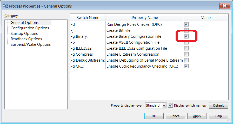
Now right click on 'Generate Programming file':

Select the Create Binary Configuration File check box and click Ok and then select Generate Programming File and right-click on it and then choose 'Run'.

The bitstream file will be created but it takes a moment, again there should be no errors. Now it's time to connect up the Elbert V2 Development board to your computer via a USB cable - Exciting times...
Then load up the ElbertV2Config program and choose the appropriate communication port for your board - finally navigate to the bitstream file just created, it will be called up_down_counter_module.bin:

Next Click program and the bitstream file will be uploaded to the FPGA:

Once complete you should see a seven segment display light up on the development board:
when 0 => Seven_Segment_Display_output(7 downto 0) := B"00000010";
when 1 => Seven_Segment_Display_output(7 downto 0) := B"10011110";
when 2 => Seven_Segment_Display_output(7 downto 0) := B"00100100";
when 3 => Seven_Segment_Display_output(7 downto 0) := B"00001100";
when 4 => Seven_Segment_Display_output(7 downto 0) := B"10011000";
when 5 => Seven_Segment_Display_output(7 downto 0) := B"01001000";
when 6 => Seven_Segment_Display_output(7 downto 0) := B"01000000";
when 7 => Seven_Segment_Display_output(7 downto 0) := B"00011110";
when 8 => Seven_Segment_Display_output(7 downto 0) := B"00000000";
when 9 => Seven_Segment_Display_output(7 downto 0) := B"00011000";
when others => Seven_Segment_Display_output(7 downto 0) := B"11111111";
end case;
Next we have a case statement - this is similar to a switch statement in a high level programming language like C. What this code does is convert the integer value of bcd into the bit value needed to drive the seven segment display.
Seven segment displays are 7 LEDS arranged in a pattern from to create an alphanumeric character. Each LED has a letter assigned to it to help us work out which LEDS to turn on to create the character.
A, B, C, D, E, F, not G, DP - this can be represented as bits like this - 1, 1, 1, 1, 1, 1, 0, 1,
And bit can be represented as a binary number = 11111101(b) which is written in VHDL as:
B"11111101";
Because the seven segment display on the Elbert V2 Development board is active low we have to invert the bits to make the segments light up:
B"00000010";
If we wanted to remove the decimal point we would change the number to:
B"00000011";
It is also possible to display the characters A to F for Hexadecimal numbers, just turn on the required segments. Here are the binary numbers for all of the characters we may need to display - I've inverted them ready for use with the Elbert V2 Development Board:
B"00000010" = 0
B"10011110" = 1
B"00100100" = 2
B"00001100" = 3
B"10011000" = 4
B"01001000" = 5
B"01000000" = 6
B"00011110" = 7
B"00000000" = 8
B"00011000" = 9
B"00010000" = A
B"11000000" = b
B"01100010" = C
B"01000010" = d
B"00001100" = E
B"00011100" = F
That's it for the counting up code - the counting down code is very similar but in reverse. If the button is held down then the value of bcd is subtracted until it reaches zero and is reset.
Here is all of the code together just in case it's needed:
library IEEE;
use IEEE.STD_LOGIC_1164.ALL;
-- define inputs and outputs
-- of the up down counter
entity up_down_counter_module is
Port (
clock_in : in STD_LOGIC;
reverse_button : in STD_LOGIC;
Seven_Segment_Enable : in STD_LOGIC_VECTOR (2 downto 0);
Seven_Segment_Display : in STD_LOGIC_VECTOR (7 downto 0)
);
end up_down_counter_module;
use IEEE.STD_LOGIC_1164.ALL;
-- define inputs and outputs
-- of the up down counter
entity up_down_counter_module is
Port (
clock_in : in STD_LOGIC;
reverse_button : in STD_LOGIC;
Seven_Segment_Enable : in STD_LOGIC_VECTOR (2 downto 0);
Seven_Segment_Display : in STD_LOGIC_VECTOR (7 downto 0)
);
end up_down_counter_module;
-- Internal signals for processing
signal bcd : integer := 0;
signal count : integer := 0;
signal clk : std_logic :='1';
begin
-- enable Seven Segment Display
Seven_Segment_Enable (2 downto 0) <="110";
-- Divide down the 12 MHz input clock to 1 Hz
process(Clock_in)
begin
if(Clock_in'event and Clock_in='1') then
count <=count+1;
if(count = 6000000) then
clk <= not clk;
count <= 1;
end if;
end if;
end process;
-- If the 1 Hz clock is high
-- and the button has not been
-- pressed and held then count up.
-- Display the count on Seven segment
-- LED display
-- if the button has been pressed
-- and held count down.
-- Display the count on Seven segment
-- LED display
process(clk) --period of clk is 1 second.
variable Seven_Segment_Display_output : std_logic_vector (7 downto 0) := (others => '0');
begin
if(clk' event and clk='1') then
if (reverse_button = '1') then
bcd <= bcd + 1;
if (bcd = 9) then
bcd <= 0;
end if;
case bcd is
when 0 => Seven_Segment_Display_output(7 downto 0) := B"00000010";
when 1 => Seven_Segment_Display_output(7 downto 0) := B"10011110";
when 2 => Seven_Segment_Display_output(7 downto 0) := B"00100100";
when 3 => Seven_Segment_Display_output(7 downto 0) := B"00001100";
when 4 => Seven_Segment_Display_output(7 downto 0) := B"10011000";
when 5 => Seven_Segment_Display_output(7 downto 0) := B"01001000";
when 6 => Seven_Segment_Display_output(7 downto 0) := B"01000000";
when 7 => Seven_Segment_Display_output(7 downto 0) := B"00011110";
when 8 => Seven_Segment_Display_output(7 downto 0) := B"00000000";
when 9 => Seven_Segment_Display_output(7 downto 0) := B"00011000";
when others => Seven_Segment_Display_output(7 downto 0) := B"11111111";
end case;
else if (reverse_button = '0') then
bcd <= bcd - 1;
if (bcd = 0) then
bcd <= 9;
end if;
case bcd is
when 0 => Seven_Segment_Display_output(7 downto 0) := B"00000010";
when 1 => Seven_Segment_Display_output(7 downto 0) := B"10011110";
when 2 => Seven_Segment_Display_output(7 downto 0) := B"00100100";
when 3 => Seven_Segment_Display_output(7 downto 0) := B"00001100";
when 4 => Seven_Segment_Display_output(7 downto 0) := B"10011000";
when 5 => Seven_Segment_Display_output(7 downto 0) := B"01001000";
when 6 => Seven_Segment_Display_output(7 downto 0) := B"01000000";
when 7 => Seven_Segment_Display_output(7 downto 0) := B"00011110";
when 8 => Seven_Segment_Display_output(7 downto 0) := B"00000000";
when 9 => Seven_Segment_Display_output(7 downto 0) := B"00011000";
when others => Seven_Segment_Display_output(7 downto 0) := B"11111111";
end case;
end if;
end if;
end if;
-- send data to seven segment display.
Seven_Segment_Display(7 downto 0) <= Seven_Segment_Display_output(7 downto 0);
end process;
end Behavioral;
Now we need to generate an implementation constraints file - this is the file that tells the compiler which pins we want to use on the FPGA device. As we are using the Elbert V2 development board we can use the schematic diagram to tell us which pins connect to what:
- Push button zero is connected to pin P80 - lets use this for the reverse_button.
- The seven segment display enable pins are connected to P120, P121 and P124 - lets use this for the seven segment enable logic vector
- The seven segment drive pins are connected P117, P116, P115, P113, P112, P111, P110 and P114.
- The 12 MHz clock is connected to pin P129.

Click next to display the summary:

Click finish to return to the main project screen - copy and paste the code below into the newly open file:
CONFIG VCCAUX = "3.3" ;
# Clock 12 MHz
NET "clock_in" LOC = P129 | IOSTANDARD = LVCMOS33 | PERIOD = 12MHz;
###################################
# Seven Segment Display #
###################################
NET "Seven_Segment_Display[7]" LOC = P117 | IOSTANDARD = LVCMOS33 | SLEW = SLOW | DRIVE = 12;
NET "Seven_Segment_Display[6]" LOC = P116 | IOSTANDARD = LVCMOS33 | SLEW = SLOW | DRIVE = 12;
NET "Seven_Segment_Display[5]" LOC = P115 | IOSTANDARD = LVCMOS33 | SLEW = SLOW | DRIVE = 12;
NET "Seven_Segment_Display[4]" LOC = P113 | IOSTANDARD = LVCMOS33 | SLEW = SLOW | DRIVE = 12;
NET "Seven_Segment_Display[3]" LOC = P112 | IOSTANDARD = LVCMOS33 | SLEW = SLOW | DRIVE = 12;
NET "Seven_Segment_Display[2]" LOC = P111 | IOSTANDARD = LVCMOS33 | SLEW = SLOW | DRIVE = 12;
NET "Seven_Segment_Display[1]" LOC = P110 | IOSTANDARD = LVCMOS33 | SLEW = SLOW | DRIVE = 12;
NET "Seven_Segment_Display[0]" LOC = P114 | IOSTANDARD = LVCMOS33 | SLEW = SLOW | DRIVE = 12;
NET "Seven_Segment_Enable[2]" LOC = P124 | IOSTANDARD = LVCMOS33 | SLEW = SLOW | DRIVE = 12;
NET "Seven_Segment_Enable[1]" LOC = P121 | IOSTANDARD = LVCMOS33 | SLEW = SLOW | DRIVE = 12;
NET "Seven_Segment_Enable[0]" LOC = P120 | IOSTANDARD = LVCMOS33 | SLEW = SLOW | DRIVE = 12;
###################################
# Switches #
###################################
NET "reverse_button" LOC = P80 | PULLUP | IOSTANDARD = LVCMOS33 | SLEW = SLOW | DRIVE = 12;
Save the file and click on the green arrow to compile the code and "Implement Top Module"

The code will now be compiled and the FPGA internal signals will be routed or implemented. There should not be any warnings or errors. Once complete you can create a bitstream file:

Now right click on 'Generate Programming file':
Select the Create Binary Configuration File check box and click Ok and then select Generate Programming File and right-click on it and then choose 'Run'.

The bitstream file will be created but it takes a moment, again there should be no errors. Now it's time to connect up the Elbert V2 Development board to your computer via a USB cable - Exciting times...
Then load up the ElbertV2Config program and choose the appropriate communication port for your board - finally navigate to the bitstream file just created, it will be called up_down_counter_module.bin:

Next Click program and the bitstream file will be uploaded to the FPGA:

Once complete you should see a seven segment display light up on the development board:
 |
| An animated GIF image of the board in action
Here is the now standard video of the board in operation:
If you wanted to get a bit more experience in coding in VHDL you could modify the program to use all three segments and count up to 999. You could also implement a simple stop-watch by adding more buttons - the possibilities are endless...
If you need the actual project files for whatever reason, here they are:
This tutorial covers quite a few useful aspects of VHDL - we have covered:
That's all for now - take care and have fun - Langster!
|
thank you so much, that was very helpful
ReplyDeletei wrote this program , but it doesnt work!!!!!
ReplyDeleteerrors :1- Object seven_seg_display of mode IN can not be updated.2-parse error, unexpected IF, expecting PROCESS (last if)
Hi, I'm sorry you are unable to get this to work. It suggests there is an issue with your code. All I can do is suggest you send me your code so that I can take a look. Zip up your project files and email them to me or share them on Google drive...
Deletei found the problem , you set Seven_Segment_Enable and Seven_Segment_Display as input.but in the source file is correct. Thank you so much for your supporting.
Deleteif you were going to add a reset button, how would you go on about it? I'm a little stuck haha
ReplyDeleteThis comment has been removed by a blog administrator.
ReplyDeleteGreat work!, But how can I use all the three segments to display for eg "100"
ReplyDelete