Sunday, 1 December 2013

Finishing the Knock Clock!

Finally it's time to complete the knock clock!  The circuit is complete, working and tested.  The firmware for the microcontroller is written and proven to work...so now is the time to put everything into a box and get on with something else.  Don't get me wrong I have had great fun making this project and I am also very interested in making more and possibly making some kits available....


So the picture above shows the PCB top layer with components and dimensions.  We can use this to design an enclosure for the project.  For quickness and because its so easy I have decided to make a laser cut box out of wood!  Laser cutting is the simplest and quickest way I have found to make unit enclosures.  As this is essentially a display piece I've decided to use laser plywood.  I'll stain and varnish it to give it a good aesthetic appeal.  This isn't really my thing in honesty.  I normally just like things to work I don't care how they look but the customer (she who must be obeyed!) has more stringent criterion...

To design the box ready for laser cutting I used Inkscape an open source graphics package which is awesome -

Inkscape

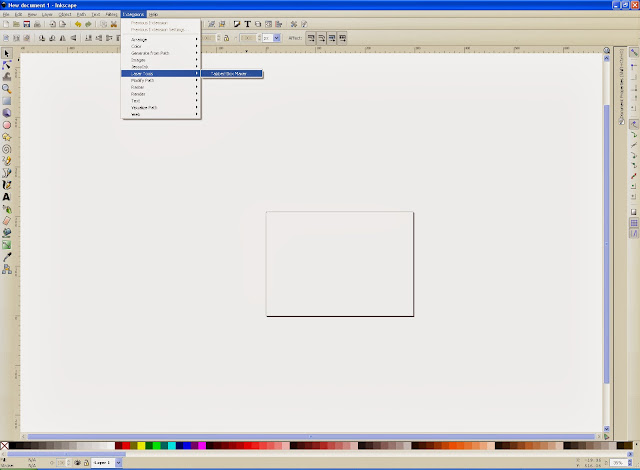
After installing and setting up the program and checking it was working I then added an extension and this is where designing boxes becomes so simple and efficient - tabbed box maker!

Tabbed Box Maker Extension for Inkscape

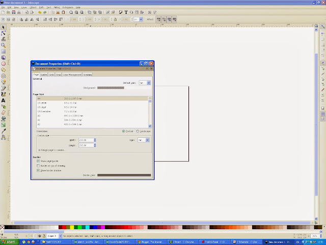
Once installed I then set my page size and limits to A4, Landscape orientation and the grid dimensions to be in millimetres...because I am a shameless Brit and use SI units and paper sizes and I have a working knowledge of those units and dimensions.  If you want to use Imperial measurements that is fine too!


Next it's time to start the tabbed box maker extension:


A window will appear with some options about the box we are going to design.


So now is the time to make some decisions about the box....We know roughly what our internal dimensions need to be...As they will be the same as the PCB.  We also need to allow some space for the solenioid to be comfortable and we need to choose how deep we want the box to be....too shallow and it will sound poor when 'knocking' but too tall is a waste of material.  In the end it's up to the designer.  Here is what I chose:


I like to work with the internal dimensions as I want to be sure whatever I'm going to put inside the box or enclosure is going to fit.  I have made mistakes before when designing enclosures by using the internal dimensions for external dimensions...All I can say is be careful and check things before cutting material or getting something made.  It can get expensive!

For the length dimension I chose 145mm...it was a guess really, I looked at the PCB and my solenoid and from the dimensions of those I surmised 145mm would be ok.  For the width I chose 100mm as it's slightly larger than the PCB and should make it fit without being too tight.  From the PCB dimensions we have 94mm width.  So if we choose to make the internal box width 100mm we have a 3mm margin between the PCB and the box walls:

100mm - 94mm = 6mm

6mm / 2 = 3mm margin

For the height I made a guess and chose 75mm.  There was no real science involved I just chose a number! 
The tab width was set to 5mm because I like having 5mm tabs.  If you choose a different value here be sure you know what you are doing.  More tabs makes the box more secure as you are providing more surface area for the glue to act upon but it can make the box very difficult to put together.

The material thickness I set to 5mm because that's the thickness of my laser plywood which I bought from an art shop in Manchester called Fred Aldous:


They sell all manner of art materials and supplies and also provide laser cutting services.

I didn't change the kerf parameter (kerf  = the amount of material the cutting action removes) and the clearance parameter I also left unchanged.

I chose a 3 piece layout style because it makes it fit a page of A4 well.  I chose the space between parts to be 2mm because I didn't want to waste material.  

When it comes time to laser cut the box we will need to cut it twice to ensure we get all of the parts we need.  
Click apply when ready and this is what the extension generates:


I saved the file at this point as I wanted to be sure that whatever changes I make from this point I can undo if I needed to.  It's always a good plan!

Next I decided to get clever...In eagle on the PCB layout section I turned all layers off on my PCB view apart from dimensions and holes.


I then exported this image as a PDF.  I then imported this image into Inkscape on a new layer.  This will allow me to set the laser cutter to drill out the holes for the PCB mounts perfectly aligning them!  I then drew some circles over the top of the hole positions and then deleted the PCB image as it isn't needed.  Finally I grouped the holes with the bottom tabbed box shape so they wouldn't move.


I love getting laser cutters to do all the work for me!  Time is precious...

Next we need to add a hole in the side of the box for the DC power Jack.  This is a bit more complicated as I don't have a 3 dimensional representation of the box.  I could model this in Google Sketchup but it isn't necessary...I can guess where the hole needs to be from the dimensions of the DC jack and the PCB layout.


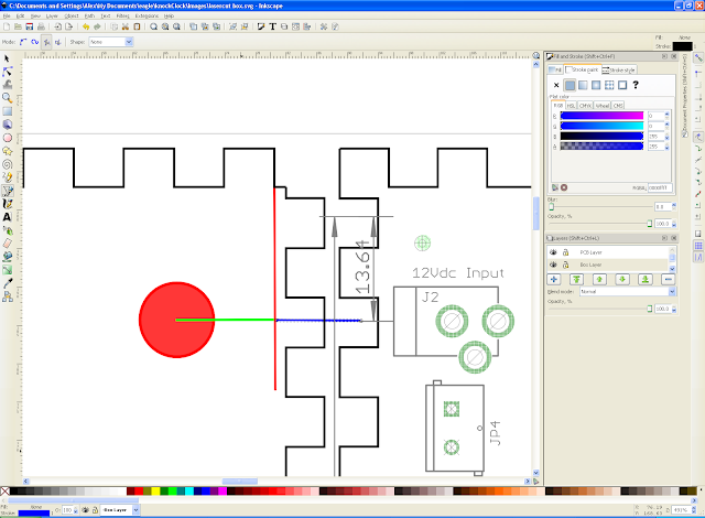
I added all of the components and a dimension from the edge of the PCB to the centre of the DC jack to help...technically not needed.  If we draw a line from the DC jack centre across to the left we can position the centre of the hole.  Next we draw another like from the edge of the tab section so that we know where the base of the side begins....I know this is difficult to understand hopefully the picture will make it clear:


The red line shows the base of the side when the box will be put together and the blue line shows where the centre of the DC jack plug will be.

What we need to do now is calculate of big a hole we need and where it needs to be positioned.  The size of the hole really depends on the size of the plug used.  I am using a 12Vdc adapter that I found in my junk pile.  I grabbed it and measured the diameter of the DC plug roughly using a ruler.  If you are making your own adapter then use the mechanical information from the datasheets!  It measured roughly 10mm and to be honest they will all be about this size.  So...Hole diameter is 10mm.

Next we need to calculate the height the DC jack will be from the base of the side.  This is where things get tricky and some luck is needed.  I used a standard DC jack socket on the PCB...I didn't even look for something specific as it's a standard part.  Here is a datasheet:

PCB Mount DC Jack Socket

From the mechanical information I know that it is 11mm tall and the height to the centre of the jack socket is 6.5mm tall.  The PCB thickness is 1.6mm and I intend using PCB stand offs 5mm tall. Therefore if we add the pertinent dimensions together we can calculate where the centre of the hole needs to be:

6.5mm + 1.6mm + 5mm = 13.1mm

So the centre of our 10mm hole needs to be 13.1mm from the base of the side.  No problem!  Lets add a 10mm hole to our side.

Lets draw another line that is exactly 13.1mm long and overlay it on top of the blue line and beginning at the red line.  Then lets add a 10mm diameter circle.


We can then delete the lines and group the hole.  Now we have a correctly positioned hole and are ready to cut the wood!

I saved the file with a different name as I will have to cut the material for six parts. One with holes and one without.  I decided to add some images to my file to make the box look a little more interesting.  The first box I designed was a little plain and boring.


If required I can provide the inkscape files so people can make their own box.

Here is a very quick video of the laser cutter in action:


Now it's finally time to put the box together.  The tabs make it very easy and all that was required was some PVA wood glue and some patience.  Once the glue set I put the PCB in the box, I was in a rush so I didn't use stand offs and the solenoid was secured with blu tac!  I will improve my version but I would recommend that people use stand offs and hot glue to secure their solenoid and PCB.

Here is the box!


In order to properly finish up this product I suppose I should provide a bill of materials and some rough costs.  So...here goes:

Part Value Device Cost (£)
       
C1 22pF Ceramic capacitor 0.04
C2 22pF Ceramic capacitor 0.04
C3 0.1uF Electrolytic Capacitor 0.036
C4 10uF Electrolytic Capacitor 0.052
C5 10uF Electrolytic Capacitor 0.052
C6 100nF Ceramic capacitor 0.028
C7 100nF Ceramic capacitor 0.028
D1 1N4001 Axial rectifier 0.056
IC1 LM7805 T0220 package  0.31
J1 Programming Header 6x 0.1' pitch header pins 0.7
J2 12Vdc power jack 3.5mm dc power jack 1.15
JP1 6 pin Header 6x 0.1' pitch header pins 0.7
JP2 5 pin Header 5x 0.1' pitch header pins 0.7
JP3 5mm Screw Terminal 5mm screw terminal phoenix connector 0.42
JP4 5mm Screw terminal 5mm screw terminal phoenix connector 0.42
KK1 Heatsink T0220 Heatsink 1.09
LED1 5mm Red LED 5mm Red LED 0.069
Q1 IRF630 MOSFET-N CHANNEL 0.57
R1 10k 1/4W axial resistor 0.018
R2 220R 1/4W axial resistor 0.016
R3 1k 1/4W axial resistor 0.017
R4 100k 1/4W axial resistor 0.017
R5 1M 1/4W axial resistor 0.017
S1 Microswitch momentary tactile switch 0.057
SP1 Piezo Buzzer Piezo Buzzer 0.37
U1 ATMEGA328P ATMEGA328P -DIP package 2.01
Y1 16MHz 16MHz crystal (through hole) 0.35
DS1307 Real time Clock Module DS1307 RTC module 7.99
PCB Circuit Board Printed Circuit Board 2.55
Total 19.873

Some of the components have to be ordered in multiples from Farnell Electronics so there would be some items left over and it would not be necessary to order three lots of header pins, one 36 row of pins would be enough.  The heatsink is also a little unnecessary for this circuit as the MosFET doesn't get hot without one. The 12Vdc 5mm screw terminal for the power input could be removed also.  If we now recalculate that brings the cost of making this device (not including enclosure) to £16.96

If we add on two sheets of laser plywood (£2.00) and time on the laser cutter (£1.00 for ten minutes) and it took about twenty minutes to cut the enclosure out:

That bring our total costs back up to £21.96!

Not too bad...It would have been nice to get the costs down below £20 and if I searched around for different suppliers I might be able to get some components more cheaply.  If I was in the business of manufacturing products I would be searching everywhere for a better deal.  I would also redesign the PCB to be smaller, use surface mount components and have the enclosures made in large numbers.  This would reduce costs considerably.

Anyway enough of the boring stuff.  I had great fun making this project and I probably will get some printed circuit boards professionally made by Seeed Studios.  Their fusion service is too good to miss!


Well that's it for now.  Enjoy people and have fun - Langster!    


Friday, 22 November 2013

Knock Clock with DS1307 continued!

Last post we designed a circuit to make a knock clock....Here is the circuit construction process:

1.  Obtain copper clad circuit board and print out bottom layer reversed on 120gm glossy paper using a laser printer.

2.  Using a clothes Iron to transfer bottom layer design to copper clad board.


3.  Once the design has been transferred soak off the excess paper with water to leave only the required copper.  Then etch the PCB using the preferred etchant - I used Ferric Chloride.


4.  After twenty minutes or so the copper should be etched away - monitor the process closely


5.  Once the etching is complete clean off the black ink using something abrasive - I used steel wool.  


6.  Finally drill out the holes using suitable drill sizes.  I used 0.8mm for every hole and then increased the FET, regulator and screw terminal holes to 1mm.

7.  Next populate the PCB with the components.  Make sure the IC socket (if you are using one) is orientated correctly along with the FET and the regulator and diode.  All of the other components are reversible.


Once that is complete we are onto the next stage.  I have to admit at this point I applied 12Vdc to the input to see if the red LED would light - it shows all of the power supply section is working - it was after I removed the LED and connected it with the correct polarity.  I always seem to get something wrong!

Next I flashed the arduino bootloader onto the ATMEL 328p chip using a dedicated ATMEL chip programmer.  There are loads of instructions available on how to achieve this:

How to flash a bootloader onto an ATMEL 328p

Once that was complete I loaded blink onto the target IC and connected an LED between MOSI and GND.  The LED flashed on and off - SUCCESS!

After that moment of awesomeness I loaded the code that I have developed earlier to achieve the knock clock functionality required.  I have to admit I had already done this as I breadboarded the circuit before populating the PCB...

Before doing all of this I populated the DS1307 adafruit RTC kit following the instructions on their website. I also then set the time on device using the serial terminal.  The instructions for doing this are:

Adafruit DS1307-real-time-clock-breakout-board-kit

The final Knock Clock code was developed from several libraries and some fairly standard programming.

Here is the code:

/*
 * Langster's Knock Clock Code
 * Forked from the TimeRTC Library example
 * The Knock Sensor Example from the Arduino Library
 * and some simple code to drive the solenoid from  
 * the FET - 22-11-2013
 */

#include <Time.h>       // Include time.h library
#include <Wire.h>       // Include Wire.h
#include <DS1307RTC.h>  // Include DS1307.h Library

byte val = 0;           // Variable to store a byte value

int solenoidPin = 9;    // FET solenoid Gate is connected to Digital pin 9
int knockSensor = A0;   // Piezo sensor attached to analogue zero            
int THRESHOLD = 10;     // integer variable that sets knock sensitivity
int hoursLoop = 0;      // integer variable for hours loop
int minutesLoop = 0;    // integer variable for minutes loop


void setup()  {
  Serial.begin(9600);         // start serial terminal at 9600 baud for debugging
  while (!Serial) ;           // wait until Arduino Serial Monitor opens
  setSyncProvider(RTC.get);   // the function to get the time from the RTC
  if(timeStatus()!= timeSet) 
     Serial.println("Unable to sync with the RTC");
  else
     Serial.println("RTC has set the system time");

  pinMode(solenoidPin, OUTPUT); //Set solenoid pin as a digital output    
}

void loop()
{
    val = analogRead(knockSensor);     // check for a knock!
    if (val >= THRESHOLD) 
    {
      Serial.println("Knock!");        // knock detected!
      if (timeStatus() == timeSet) 
      {
        digitalClockDisplay();         // display the time on the serial terminal
        actuateSolenoid();             // Drive the FET to actuate the solenoid
      } 
    else 
      {
        Serial.println("The time has not been set.  Please run the Time");
        Serial.println("TimeRTCSet example, or DS1307RTC SetTime example.");
        Serial.println();
        delay(4000);
      }
    }  
}

void digitalClockDisplay(){
  // digital clock display of the time
  Serial.print(hour());
  printDigits(minute());
  printDigits(second());
  Serial.println(); 
  delay(500);
}

void printDigits(int digits){
  // utility function for digital clock display: prints preceding colon and leading 0
  Serial.print(":");
  if(digits < 10)
    Serial.print('0');
  Serial.print(digits);
}

void actuateSolenoid()
{
int convertHours = hour();  //convert from 24hour clock to 12 hour clock 
    if (convertHours > 12)
        {
          convertHours = convertHours - 12;
        }
  
  Serial.print("convertHours: ");
  Serial.print(convertHours);
  Serial.println(" ");
  
  //drive FET to actuate solenoid for number of hours
  
  for (hoursLoop=1; hoursLoop <= convertHours; hoursLoop++)
    {
       Serial.print(hoursLoop);
       Serial.println(" ");
       digitalWrite(solenoidPin, HIGH);
       delay(500);
       digitalWrite(solenoidPin, LOW);
       delay(500);
    } 
    
    delay(1000);  //pause between hours knocks and minutes knock

  int convertMinutes = minute();         //convert minutes to tens of minutes
  convertMinutes = convertMinutes / 10;
  
  Serial.print("convertMinutes: ");
  Serial.print(convertMinutes);
  Serial.println(" ");
  
  //drive FET to actuate solenoid for number of minutes
    
    for (minutesLoop=1; minutesLoop <= convertMinutes; minutesLoop++)
    {
       Serial.print(minutesLoop);
       Serial.println(" ");
       digitalWrite(solenoidPin, HIGH);
       delay(500);
       digitalWrite(solenoidPin, LOW);
       delay(500);
    }

}

The code pretty simple and the comments should explain each section clearly.  Essentially the arduino constantly polls the piezo sensor for a knock.  If a knock is detected the time is read from the real time clock device (DS1307).  The Hour data is then converted from 24 Hour clock format to 12 Hour format and the Solenoid is actuated for the number of Hours.  There is a short delay and then the minutes data is converted to tens of minutes and again the solenoid is actuated for the number of minutes.  The program then loops back to the start polling the piezo sensor for another Knock!

I will post a video of the circuit working when I get a chance!  The next post will discuss making a laser cut box for the Knock Clock before final assembly!  That is it for now though - Enjoy Langster!


Sunday, 17 November 2013

Knock Clock Using DS1307 and an Arduino

Knock Clock!

A Knock Clock is a electro mechanical clock which tells the 'knocker' the time in audible 'knocks' to +/-10 minute accuracy.  My better half saw one of these recently and asked me to make her one.  This is my own implementation based on a circuit made by a member of the Manchester Hackspace - Paul Plowman!

The device itself is a basically a box with some electronics and a device for striking the side of the box to create the 'knock' sound.  In this case I am using an electromagnetic plunger known as a solenoid.  It is normally used to control valves or mechanical devices from an electronic controller.  An electro-mechanical relay is essentially made up of a solenoid and a switch.  More information about solenoids can be found via the internet and wikipedia!

Wikipedia's entry on Solenoids

The basic idea of the circuit is, as with most electronics:

  • Take an input (the user 'knocking on the enclosure). 
  • Process this input (tell the processor to output the current time). 
  • Provide some form of output (cause the solenoid to actuate the time in hours and tens of minutes).

In this case the input is going to be sense the user knocking on the enclosure using a piezo buzzer as a simple microphone.  Piezo crystals are a useful electrochemical crystalline structure which when force is exerted on the structure a high voltage low current signal is generated.  It is the main component used is electric stove gas lighters and certain types of cigarette lighter.  More wikipedia below:

Piezoelectricity

Once the input has been detected it is necessary to process this input and then provide an output.  To this end I am going to use the ever popular Atmel 328P microcontroller with the arduino bootloader.  However I am not going to design a shield this time as I wanted to try to keep the cost of construction down.  Using an arduino main board for every project can get expensive - even using clones is becoming expensive!  So we have an input which we then need to compare to a known value - time!  How does the microcontroller know what the time is?  We could set the time on the microcontroller via the serial terminal each time the device is connected to a computer or we could use an ethernet controller and use the same technique; we could hard code the time from when the microcontroller was programmed and use that - best make sure the power is never removed!  Or we could use a real time clock...I have decided to use a real time clock as this is in my opinion the best method to use ensuring that the clock keeps reasonable time.

Real time clocks are special integrated circuits which communicate via the I2C protocol directly to the microcontroller and are battery backed up which means that they are constantly powered by a small battery and never lose the time (once it has been set) even if power to the main circuit is removed.  The accuracy over time is not always great (they lose a second each month) and the battery normally lasts about 5 years. There are several real time clock modules available to buy and rather than implement the circuit for myself I have bought one of these modules to save time.  The real time clock device used in the module is based on the ubiquitous DS1307 by Maxim Semiconductor.

DS1307 datasheet

The module I am using was provided by the excellent and very helpful Adafruit Industries:

DS1307 RTC Kit

Now that we have a method of receiving and processing the input it is necessary to drive the output - a solenoid. Solenoids are fairly common devices and can be treated in much the same was as a relay - although a power hungry relay!  It often takes a lot of current to drive a solenoid and the circuit will need to provide significant power (voltage and current) in order to make the solenoid actuate.  The best way to achieve this is to use a Field Effect Transistor.  I have discussed FETS in previous blog posts so I'm not going to go through this again - please read my previous posts.

We need an N-Channel metal oxide silicon field effect transistor ( N-MOSFET) with the following parameters:

Vds - 12V - I have decided to use 12V as the main voltage input
Vgs threshold - up to 5V - we need a logic level FET capable of being driven from the microcontroller
Ids - 1A or higher - we need a device capable of driving the Solenoid
T0220 Package - I like big through hole parts - they are easy to solder!   

There are probably over a hundred devices that meet these requirements.  If we do a search using Farnell Electronic's parametric search facility the following results are found:


We could use any of these N Channel-MOSFET devices and the VGS threshold voltage is the most important parameter as we need the device to work from a 5V digital signal from the microcontroller.  As we don't have any particular preference I am going to choose the least expensive device to keep costs down and the cheapest device is one I already own!

The device I have chosen is the IRF630 by ST Microelectronics - the datasheet is below:

IRF630 Datasheet

It meets all of the requirements and costs a very reasonable £0.56 from Farnell Electronics.

So....we now have all of the parameters for the Knock Clock decided we can go ahead and design the circuit.  I have decided to use a basic implementation of the arduino using an Atmel 328p.  The circuit will not have the serial to USB converter or a method of programming the microcontroller so we will have to provide a method of programming and talking to the microcontroller.  The rest of the circuit is standard boiler plate electronics - A 12V to 5V linear regulator, a piezo electric speaker (being used as a microphone) and a MOSFET driving a solenoid.  The centre header is for the real time clock module. The circuit is shown below:

 
I have included a six pin programming header to initially 'flash' the arduino bootloader onto the microcontroller and a header to allow communication with the microcontroller via a USB to serial cable.  The 12Vdc input will be provided via a standard dc barrel jack or via 5mm screw terminals.  The output to the solenoid is provided also via 5mm screw terminals.

Here is the PCB layout for the bottom layer:


Here is the top layer with the component identification:


The bill of materials for this project is as follows:

Part Value Device Description
       
C1 22pF Ceramic capacitor Capacitor
C2 22pF Ceramic capacitor Capacitor
C3 0.1uF Electrolytic Capacitor Capacitor Polarized
C4 10uF Electrolytic Capacitor Capacitor Polarized
C5 10uF Electrolytic Capacitor Capacitor Polarized
C6 100nF Ceramic capacitor Capacitor
C7 100nF Ceramic capacitor Capacitor
D1 1N4001 Axial rectifier Diode
IC1 LM7805 T0220 package  Voltage Regulator
J1 Programming Header 6x 0.1' pitch header pins 6 pin I2C programming header
J2 12Vdc power jack 3.5mm dc power jack Power Jack
JP1 6 pin Header 6x 0.1' pitch header pins Serial Communications Header
JP2 5 pin Header 5x 0.1' pitch header pins RTC Header
JP3 5mm Screw Terminal 5mm screw terminal phoenix connector 12Vdc input from screw terminals
JP4 5mm Screw terminal 5mm screw terminal phoenix connector Solenoid output from MOSFET
KK1 Heatsink T0220 Heatsink Heatsink for MOSFET
LED1 5mm Red LED 5mm Red LED Power LED
Q1 IRF630 MOSFET N-CHANNEL Common logic level MOSFET
R1 10k 1/4W axial resistor Resistor
R2 220R 1/4W axial resistor Resistor
R3 1k 1/4W axial resistor Resistor
R4 100k 1/4W axial resistor Resistor
R5 1M 1/4W axial resistor Resistor
S1 Microswitch momentary tactile switch Momentary Switch for reset
SP1 Piezo Buzzer Piezo Buzzer Piezo Buzzer used as a microphone
U1 ATMEGA328P ATMEGA328P - DIP package Microcontroller with arduino bootloader
Y1 16MHz 16MHz crystal (through hole) 16MHz Crystal for microcontroller

Just for fun I used an online gerber viewer to show what the printed circuit boards will look like if manufactured:

Here is the Bottom Layer
Here is the top layer:
Well that is about all for now.  In the next post I will show pictures of the actual construction and then finally I'll go through the programming of the firmware for the microcontroller.  Enjoy - Langster!


Sunday, 6 October 2013

How do Switch-Mode Boost Converters Work

I recently made my own version of the adafruit Minty Boost circuit.  It's a battery powered DC to DC converter that takes 2x 1.5V AA batteries and converts that to 5V USB output.  It's a damn useful circuit particularly for use charging mobile telephones when the internal battery is running flat!  I find it slightly more useful than commercial versions of the same device because rather than using a lithium polymer battery this version uses off the shelf AA batteries which are nearly always available from any shop anywhere!  Lithium polymer batteries need special charging circuits and don't like being over and undercharged which is easily done.

The original circuit and some very good documentation and kits are available here:

MintyBoost V3.0 - Very cool stuff from Adafruit Industries!!!

The circuit is a switch-mode dc to dc converter.  I haven't talked about switch-mode power supplies before so here goes!  This might get complicated....bear with me!

Power supplies can be realised in several different forms:

Step UP - Increase voltage or current
Step Down - reduce voltage or current
ac - alternating current
dc - direct current
Linear - conversion in a straight line...see previous posts
Switch-mode - use a combination of an inductor, zener diode and capacitor to provide a different voltage than the input.

Switch-mode power supplies are based on an electronic trick...What they do is take energy in one form and convert it to another form to get the desired output.  How they work is they take a dc voltage source (input) convert it to a pseudo alternating signal (square wave or pulse width modulation) and pass that signal through a combination of an inductor, switching diode and capacitor.  The way the inductor diode and capacitor are connected denotes the type of switch-mode power supply.  This is known as the switch-mode topology....Some examples of these are:

Buck (Step Down)
Boost (Step Up)
Flyback (Step Up)

A Buck regulated switch-mode power supply (SMPS) would take in say 12 V and give out 5 V at a steady current.

A Boost regulated SMPS takes in say a 3 V input and boosts it to 5 V

The circuit topology depends on how much power or energy the circuit designer requires.  SMPS are popular because they are more efficient than linear power supplies and use smaller and cheaper components. The drawback of switch-mode power supplies is that they have inherent electronic switching noise which can affect sensitive instrumentation circuitry.

Wikipedia has a great entry on how boost converters work:

http://en.wikipedia.org/wiki/Boost_converter

Here is a quick example simulation I made up just to show how boost converters work.  Essentially what they do is increase the output voltage by taking the input voltage, creating a switching waveform and passing that signal through an inductor, switching (Schottkey) diode and a large electrolytic capacitor.  By doing this the energy in the switching waveform is held as magnetic energy in the inductor for a very short period of time.  This energy then charges the capacitor up.  When the switching waveform changes polarity the energy in the capacitor is dumped to the output...this energy dumping is seen by the output as an increased voltage. The classic water analogy would be filling a large water tank very quickly with low pressure and then emptying it all in one go giving the impression there is more water pressure present at the output than at the source.

Here is the circuit:


Here is a simulation video showing the various parts of the circuit and the switching and output waveforms on an oscilloscope.


The section containing the signal generator and the TIP41CG transistor can be combined into a single integrated circuit called a boost converter.  The IC used in the circuit by Adafruit Industries in the mintyBoost was an LT1302 micropower Boost Converter.  Its a very useful device if a little expensive! It basically combines the chopper signal generator and switching transistor into one single device which is easy to use.

LT1302 product page

Here is the schematic diagram for the Adafruit minty Boost....I have redrawn it for my own nefarious purposes.  The component values and types are exactly the same as Adafruit used.


Here is my PCB layout.  It uses a single sided PCB to make it easy to etch using the toner transfer method


Just for fun I rendered the PCB in google Sketchup to show how the device will look once I have populated


Here it is again with a 2xAA battery holder and some mechanical dimensions - Renders are Cool!


These renders are very useful as they show the designer very clearly if the components will all fit together and not foul on each other.  It also makes it easy to design an enclosure for the circuitry once the design has been constructed and tested....something I really struggle with :(

Anyway....I made the circuit for real....for once it worked first time!  I am not surprised however as all of the hard work was done for me by Limor Fried of Adafruit industries....they do excellent work - Please check them out!

Here is a picture of the realised circuit!  The photograph is of a previous version I made with the PCB elongated to hold the battery compartment.  I decided to shorten the PCB for this version to reduce costs!


That's it for now.  Enjoy - Langster!


Saturday, 20 July 2013

Arduino LC Meter Shield

A short distraction from the Signal Generator project to make an LC Meter Shield!

It has been a considerable time since I posted.  Blogging does not come naturally for me and I often prefer to just do things rather than write about them.  I still haven't finished the Signal Generator although to be honest it is close....I am lacking motivation.  I have pushed that project down a route which is no longer palatable... 

Instead I have decided I will write about a small project that I made recently which works well and was great fun (for me) to make and build.  I always need test equipment....it's a strange thing with Engineers...they need toys to make bigger toys!

In order to measure Capacitance and Inductance a piece of test equipment is often used called an LC Meter.  This is a device which measures the amount of Henries an inductor has (Henries is the unit of inductance) or the amount of Farads in a capacitor (Farads is the unit of capacitance).

Inductor - an electronic component that stores energy for a short period of time by generating a magnetic field - normally made by making a coil of wire around a former.  Sometimes special cores are used to improve the inductor's frequency response.  Inductors are sometimes called chokes!

http://en.wikipedia.org/wiki/Inductors

Capacitor - an electronic component that stores energy for a short period of time by producing an electrostatic field on two metal plates.  The size of the plates and the distance between the plates changes the amount the of capacitance the component will have.  The dielectric material between the plates also has an effect of the amount of capacitance.

http://en.wikipedia.org/wiki/Capacitor

I needed a way of verifying that the electronic components I bought or made are within the specifications I require!  Component manufacturers print the nominal level of what the inductor or capacitor is but this varies considerably between batches and is often considerably off.  Every good engineer needs a way of checking that parts are what they say they are...

There are plenty of hobbyist projects available on making an LC meter.  This is my interpretation.  If you do a search in google for 'LC meter circuit' several pages will be sourced immediatly.

I was directly inspired by Kerry Wong's blog post -

Kerry Wong's Blog about an LC Meter

There was also an article in Everyday Practical Electronics issue in March 2010 using a PIC Microcontroller.

I decided to make an LC Meter which uses the arduino shield form factor and is easy to make and use.  I'm hoping people will like it and use it...although most electronics hobbyists I know nowadays are all digital and no analogue - ho hum!

Most LC meter instruments use a free running oscillator at a known frequency.  When the user inserts the component in question in parallel with the oscilllator  the frequency changes. By comparing the new frequency with the old frequency and using some mathematics the value for the component can be obtained.

So....how do we make an oscillator?  There are several methods and I have discussed this in previous blog posts.  This project uses a comparator to make a square wave oscillator.  The circuit is below:


The oscillator section is made up of the 100uH inductor and the 4.7nF Capacitor.  These two components decide the frequency of oscillation.  All the other components are to make the oscillator work and to provide a method of making measurements.

The formula for calculating the frequency of oscillation and the other formulae used in the project are below:


lets calculate the frequency of our oscillator:

L = 100 uH or 100 * 10^-6 H
C = 4.7 nF or 4.7 * 10^-9 F
PI = 3.142..

Therefore F = 1 / 6.284 * SQRT (100*10^-6 * 4.7*10^-9)

F = 232.121 kHz

lets say 232 kHz.

So our oscillator will free run at 232 kHz using the above inductor and capacitor.  If we then introduce another component into the oscillation this frequency will change and we can use the original frequency and information about the oscillator components to calculate what value the new component has.

Here is a short simulation video showing how the measurement stage works:


Now that we have a method of measuring the components we need a way of controlling the circuit and displaying the information.

To this end I am going to use the popular arduino platform because its a great piece of hardware for rapid prototyping!  Here is the rest of the circuit:


The circuit is fairly boiler plate electronics.  The frequency of the oscillator is measured by the arduino on pin 5.  The firmware uses a special arduino frequency counter library - more on this later.  The type of measurement is controlled by a switch selecting which type of component is being measured and then we also have two buttons for displaying the current frequency of oscillation or measurement function (which controls a relay) and a calibration / zero button.  We finally have an 16x2 LCD display being controlled by the arduino to display the information.

Once I had prototyped the circuit and checked it worked - briefly I laid out a PCB and etched a circuit board.  Here is the layout:
Top Layer with component placement
PCB Bottom Layer

I then etched and drilled the PCB and populated it with components.  I was so excited I plugged it onto my arduino and tried to get it working straight away...It didn't but that's not surprising.  If a project works first time nobody learns anything!  Sometimes though I do wish projects would work first time - particularly at work!

The problems were minor and have been fixed in the layout so if I decide to make another version it will work first time - Here is a link to the Eagle files and other associated information:

Google Drive link to LC Meter Eagle project - LM339 version

Once I had checked that the oscillator was working with an oscilloscope I got on with writing the source code.  I'm not the best programmer in the world so I used a lot of other people's work to get this circuit to work as intended.  Kudos to Kerry Wong and his version of this project!

The reason this project is viable is because of the frequency counter library made and maintained by Peter Welter-Platz

http://interface.khm.de/index.php/lab/experiments/arduino-frequency-counter-library/

Updated Library for use with the latest Arduino IDE:

http://interface.khm.de/wp-content/uploads/2009/01/FreqCounter_1_12.zip

Updated Library for the reading the Button presses:

Its a great library and it makes it very easy for people to measure frequency of signals with their arduino.  Basically I believe the library works by comparing the frequency to be measured with one of the internal microcontroller timers.  The result is then stored and available for interrogation.

http://downloads.arduino.cc/libraries/github.com/madleech/Button-1.0.0.zip

In order to get the code to compile you will need to download the latest versions of these libraries and install them using the Arduino IDE.

Here is the code...it's not perfect but it does work:

/*
  Langster's LC Meter Code - 09-06-2019
  Uses the LCD library, Frequency Library 
  Button libary and various other bits and pieces

  Updated the code for use with updated libraries etc.
  
  V2.0 
  
  This code borrows from Kerry Wongs LC Meter
  code!
  
  To Calibrate press both the Frequency and 
  Calibrate buttons together!
  
  To measure frequency press the frequency
  button
  
  Enjoy!
   
 */

// Include the Frequency counter library
#include <FreqCounter.h>

// Include the Button Library
#include <Button.h>

//part of the switch position check
enum meterMode {
    L,
    C,
    F
};

unsigned long indFreq = 23896;   //rough frequency from oscilloscope measurements
unsigned long capFreq = 23885;   //rough frequency from oscilloscope measurements

long measureComponentFreq = 0;   //variable to store component measurement frequency

float cMeasured;                 //Th measured capacitance
double lMeasured;                //The measured inductance

float cMeasuredZero;             //The zero factor for capacitance
double lMeasuredZero;            //The zero factor for inductance

//Some temporary variables for calculations

long temp1;
long temp2;
double temp3;

const float Cth = 4.7 * 1e-9;    //measured 4.7nF - calibration capacitor value
const float Lth = 91.14 * 1e-6;  //measured 91.14uH - calibration inductor value

int i=0;                         // count variable
int switchState;                 // variable for storing the state of the switch

unsigned long frq;               //The frequency measurement
long capFreqArray[10];           //An array for storing frequencies
long indFreqArray[10];           //An array for storing frequencies

long frqAverage = 0;             //An variable for averaging
long average = 0;                

const int frequencyButtonPin = 16;     // the number of the pushbutton pin
const int calibrateButtonPin = 15;     // the number of the pushbutton pin
const int relayPin = 14;               // the number of the relay pin
const int componentSelectPin = 2;      // the number of the component select pin
const float pi2=6.283185307;

Button calibrationButton = Button(15);  //Calibration button on pin 15 or A1
Button frequencyButton = Button(16);    //Frequency button on pin 16 or A2

meterMode currentMode;                  //check which mode the switch is in

// include the LCD display library:
#include <LiquidCrystal.h>

// initialize the library with the numbers of the interface pins
LiquidCrystal lcd(12, 11, 10, 9, 8, 7);

//Check the switch position

void checkLCMode() {  
    
    switchState = digitalRead(componentSelectPin);
    
    if (switchState==LOW) {
        currentMode = L;
        lcd.setCursor(0, 0);
        lcd.print("Mode: L    ");
        measureInductance();
        
    } else {
        currentMode = C;
        lcd.setCursor(0, 0);
        lcd.print("Mode: C    ");
        measureCapacitance();
    }

}

//setup the arduino

void setup() {
  // set up the LCD's number of columns and rows: 
  lcd.begin(16, 2);

  pinMode(relayPin, OUTPUT);
  
  pinMode(calibrateButtonPin, INPUT);
  pinMode(frequencyButtonPin, INPUT);
  pinMode(componentSelectPin, INPUT);
  
  digitalWrite(componentSelectPin, HIGH);
  
  Serial.begin(57600);        // connect to the serial port
  digitalWrite(relayPin, HIGH); 

  lcd.setCursor(0, 0);
  lcd.print(" ** LC Meter ** ");
  
  //measureCalibrationCapacitance();
  //measureCalibrationInductance();
    
  delay(2000); 
  
  lcd.clear();
   
}  

void loop()
{
  //check if calibration is required
  
  if(calibrationButton.pressed() && frequencyButton.pressed())
  {
    switchState = digitalRead(componentSelectPin);
    
    if (switchState==LOW) 
      {
          currentMode = L;
          lcd.setCursor(0, 0);
          lcd.print("Short Terminals");
          lcd.setCursor(0, 1);
          lcd.print("Press Cal Button");
          
          if(calibrationButton.pressed())
            {
              measureCalibrationInductance();
            }
  
      } 
    
    if (switchState==HIGH) 
  
      {
          currentMode = C;
          lcd.setCursor(0, 0);
          lcd.print("Clear Terminals");
          lcd.setCursor(0, 1);
          lcd.print("Press Cal Button");
          
          if(calibrationButton.pressed())
            {
              measureCalibrationCapacitance();
            }
      }
      
  }
  
  //check if frequency measurement is required
  
  if(frequencyButton.pressed())
      {
        measureFrequency();
        digitalWrite(relayPin, HIGH);
      }

checkLCMode();    //check switch position
  
  
}

//Measure the frequency

void measureFrequency()
{

    digitalWrite(relayPin, LOW);
  
    FreqCounter::f_comp=10;   // Cal Value / Calibrate with professional Freq Counter
    FreqCounter::start(100);  // 100 ms Gate Time
    while (FreqCounter::f_ready == 0) 
    frq=FreqCounter::f_freq;   
    
    lcd.setCursor(0, 0);
    lcd.print("Frequency ");
    
    lcd.setCursor(0, 1);
    lcd.print("F: ");
    lcd.print(frq);
    lcd.print("      ");
     
    delay(4000);
    
}

//Calibrate for inductance measurements

void measureCalibrationInductance(){

    for (int i=0; i<100; i++)
        
        {
          FreqCounter::f_comp=10;   // Cal Value / Calibrate with professional Freq Counter
          FreqCounter::start(100);  // 100 ms Gate Time
          while (FreqCounter::f_ready == 0) 
          frq=FreqCounter::f_freq;
          indFreq=frq;
          
          temp1 = sq(indFreq);
          temp2 = sq(measureComponentFreq);
          temp3 = float(temp1)/float(temp2);
          lMeasured = Lth*(temp3-1);
          lMeasuredZero = lMeasured;
          i++;
          
        }
      
      lcd.setCursor(0, 0); 
      lcd.print("Calibration     ");
      lcd.setCursor(0, 1);
      lcd.print("Complete        ");
      delay(4000);
      
      lcd.clear();
    
}

//Measure the inductance

void measureInductance()

{
      FreqCounter::f_comp=10;   // Cal Value / Calibrate with professional Freq Counter
      FreqCounter::start(100);  // 100 ms Gate Time
      while (FreqCounter::f_ready == 0) 
      frq=FreqCounter::f_freq;
      measureComponentFreq=frq;
      
      delay(200);
      
      calcIndData();

}


//Calculate and Display the Inductance

void calcIndData(){
    
    temp1 = sq(indFreq);
    temp2 = sq(measureComponentFreq);
    temp3 = float(temp1)/float(temp2);
    lMeasured = Lth*(temp3-1) - lMeasuredZero;
    
    lcd.setCursor(0, 1);
    lcd.print("L: ");    
        
     if (lMeasured >= 1e-9 && lMeasured < 1e-6) 
            {
                lMeasured = lMeasured * 1e9; // nano
                lcd.print(lMeasured);
                lcd.print(" ");
                lcd.print("nH");
                lcd.print("        ");
            } 
            
            if (lMeasured > 1e-6 && lMeasured < 1e-3) 
         
            {
                lMeasured = lMeasured * 1e6; // micro
                lcd.print(lMeasured);
                lcd.print(" ");
                lcd.print("uH");
                lcd.print("        ");
            }
            
            
            if (lMeasured > 1e-3) 
            
            {
                lMeasured = lMeasured * 1e3; // milli
                lcd.print(lMeasured);
                lcd.print(" ");
                lcd.print("mH");
                lcd.print("        ");
            }
  
}  

//Measure the Calibration Capacitance

void measureCalibrationCapacitance()
{
  for (int i=0; i<100; i++)
        {
          FreqCounter::f_comp=10;   // Cal Value / Calibrate with professional Freq Counter
          FreqCounter::start(100);  // 100 ms Gate Time
          while (FreqCounter::f_ready == 0) 
          frq=FreqCounter::f_freq;
          capFreq=frq;
          
          temp1 = sq(capFreq);
          temp2 = sq(measureComponentFreq);
          temp3 = float(temp1)/float(temp2);
          cMeasured = Cth *(temp3-1);
          cMeasuredZero = cMeasured;
          i++;
        }
     
     lcd.setCursor(0, 0); 
     lcd.print("Calibration     ");
     lcd.setCursor(0, 1);
     lcd.print("Complete        ");
     delay(4000);
     
     lcd.clear();
     
}


//Measure the capacitance

void measureCapacitance(){
    
      FreqCounter::f_comp=10;   // Cal Value / Calibrate with professional Freq Counter
      FreqCounter::start(100);  // 100 ms Gate Time
      while (FreqCounter::f_ready == 0) 
      frq=FreqCounter::f_freq;
      measureComponentFreq=frq;
      
      delay(200);
      
      calcCapData();
    
}

//Calculate and display the capacitance
  
void calcCapData(){
    
    temp1 = sq(capFreq);
    temp2 = sq(measureComponentFreq);
    
    temp3 = float(temp1)/float(temp2);
    cMeasured = Cth*(temp3-1)-cMeasuredZero;
    
    Serial.print("Capacitor Oscillator Frequency: ");
    Serial.print(capFreq);
    Serial.println();
    Serial.print("Component Oscillator Frequency: ");
    Serial.print(measureComponentFreq);
    Serial.println();
    Serial.print("Cap Osc Squared: ");
    Serial.print(temp1);
    Serial.println();
    Serial.print("Msr Osc Squared: ");
    Serial.print(temp2);
    Serial.println();
    Serial.print("Division       : ");
    Serial.print(temp3);
    Serial.println();
    Serial.print("Component Value: ");
    Serial.print(cMeasured);
    Serial.println();
    
       
    lcd.setCursor(0, 1);
    lcd.print("C: ");
        
     if (cMeasured < 1e-9) 
            {
                cMeasured = cMeasured * 1e12; // pico
                lcd.print(cMeasured);
                lcd.print(" ");
                lcd.print("pF");
                lcd.print("       ");
            } 
            
     if (cMeasured >= 1e-9 && cMeasured < 1e-6) 
            
            {
                cMeasured = cMeasured * 1e9; // n
                lcd.print(cMeasured);
                lcd.print(" ");
                lcd.print("nF");
                lcd.print("       ");
            }  
            
      if (cMeasured > 1e-6)      
            {
                lcd.print("Out of Range");
                lcd.print("        ");
            } 
    
} 

It's long and it isn't pretty but it should be fairly simple to understand.  The program sets up the libraries, variables and the buttons and LCD display.  It then looks at which position the user component select switch is in and then performs the required measurement.  If the user presses the frequency button the current frequency of the oscillator is displayed.  If the user presses and holds both buttons and then follows the on screen instructions the unit calibrates.  In order to calibrate the L mode the input terminals have to be shorted together.  For capacitance mode the terminals must be open and not connected to anything.

Here is a video of the completed unit running on my arduino Uno in use.


There are things about the LC meter that I would do differently - there always are!  I would prefer the device to have a larger measurement range - Inductors are ok but the capacitance range of up to 1 µF is not helpful.  I often like to measure electrolytic capacitors and this unit can't do that.  In order to achieve that I need to implement a frequency divider circuit on the measurement frequency pin so that I can then use a smaller measurement capacitor which increases the range.  I would also like to add another relay which automatically shorts the measurement terminals so that when calibrating the inductor range the user doesn't have to short the terminals.  All told though this came out very well! 

Update: I got some valuable feedback from a reader who asked if it would be possible to implement the analogue section using a dual comparator.  It is possible and I have selected the LM393 dual comparator to do this.  Here is the full schematic:


I hope this helps people make their own versions of the circuit!  Here is a link to the LM311 Eagle Files:

LC Meter - LM311 Version Eagle Files

Further Updates:

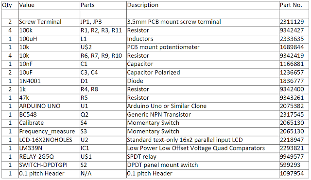
I have had some feedback from quite a few people regarding this post...my most popular project yet! I have decided to help out by giving the bill of materials:


All of the part numbers are for Farnell Electronics.  I suggest people shop around for various parts as they can be found cheaper elsewhere - particularly the 16x2 LCD display and the Arduino.

Here is some 3D renders of the circuit I made using Eagle and Sketchup! I also made a case which can be 3D printed.


Update - A lot of people have been building this project (which is great!) but are sometimes struggling to check things are working as intended. If you have access to an oscilloscope you can measure the oscillation frequency by connecting the oscilloscope probe ground lead to any 0V reference on the circuit (I use the ground plane normally) and then connect the probe tip to pin 2 of the LM339 or pin 3 of an LM311.  Ensure that the measurement terminals are open (nothing is connected to them and the unit is in capacitance mode.  If the same 100 uH inductor and 4.7 nF capacitor have been used it should be possible to see the following waveform:

LC Meter Oscillator on Pin 2 with terminals open
If you want you can then short the terminals together and change the select switch and you should see exactly the same waveform!

The oscilloscope was set to 5 volts / division on the Y axis and the time base was set to 2 micro-seconds per division for the X axis.  The trigger level was set to 1 Volt and the channel was set to measure a DC signal.  Good Luck!