Recently I have been learning to use 3d CAD packages so that I can design and build some cases and enclosures for these electronics projects I have been writing about here. I have been using an EagleCad ULP (user language program) called eagleUp 4.4. It provides a way of rendering the PCB layout with components so that it can be viewed in Sketchup.
Once you have the programs installed and setup it really is very simple to render your PCB into a 3d image so that you can view the 'populated' PCB and design mechanical enclosures ready for manufacture by 3d printing or using a laser cutter.
You will also need to obtain a copy of Sketchup Version 8
I would install the programs as directed before continuing! You will need to follow the instructions to tell sketchup where the eagle up addon is so that it's possible to load the .eup file into sketchup. Don't worry it isn't hard!
I recently designed a version of the LC Meter for one of the blog readers using an LM311 comparator. It uses exactly the same firmware as in the previous post but instead of using an LM339 quad comparator it uses an LM311 dual comparator. The circuit works in exactly the same way as the previous version. If people wish to know how it works they should check out the previous post:
Here is the Schematic Diagram:
Here is the PCB bottom layer:
The bottom layer is mirrored here so that it can be printed ready for toner transfer to manufacture the PCB. It doesn't show whether any components are over lapping or fouling or how the top side of the PCB will look once populated with components. This is where eagleUp 4.4 comes in handy!
In the eagle PCB layout screen click on the run ULP Icon:
Now select eagleUp_export.ulp from the open dialog box:
The following window will appear:
These are the parameters which can be changed depending on your requirements:
Image Export - the amount of pixels present in the render - the higher the dpi the larger the file size and the longer it will take to render the PCB
Outline Layer - select which the layer the image will use as the dimension
Silk Layers - Select whether you wish for the silk screen to be present and to use both place diagrams and component names and identifications or not at all
Misc - Choose whether you wish to render the PCB with or with components and vias
Board Thickness - The physical thickness of the glass fibre substrate supporting the copper tracks and components
Choose solder mask color - Which colour (I'm british!) should we use for the etch resist - most people use green but OSH park like to use purple! It's up to the user...
Choose plating - what colour do you want the tracks to be....I always choose gold but again it's up to the user.
Choose silk color - What colour will the silk screen be...Again I always choose white but it's the user's choice.
When ready click Ok and wait for the magic to complete - this may take some time although for most boards it was less than 2 minutes. The PCB and components are being rendered and placed on the PCB in a sketchup image.
Load up Sketchup 8 and click on the plugins menu Item import eagleUp v4.4
Then when the dialog box appears navigate to the appropriate eagle directory for the project
Mine was callled LC Meter dif Ver...
Inside that eagle project folder there will now be a folder labelled eagleUp. Select that folder and then select the .eup file inside it.
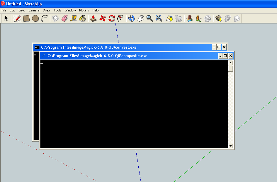
Once you click open again be prepared for a short wait of about two minutes...the program is running a script file which is placing the components and rendering the image.
Once the process has completed you will probably be presented with the following dialog box:
If we look closer at the dialog box it's telling us that the program did not have sketchup models with the correct names to place them on the PCB. Make a note of all of the names in the dialog box as we will need this information for later:
Click ok when ready. We are now going to find suitable models for the missing parts and then label the files with the correct names so that when if we were to re-run the import eup script all the missing items would be found and rendered correctly.
Click on the file menu in sketchup and navigate to the 3d warehouse section:
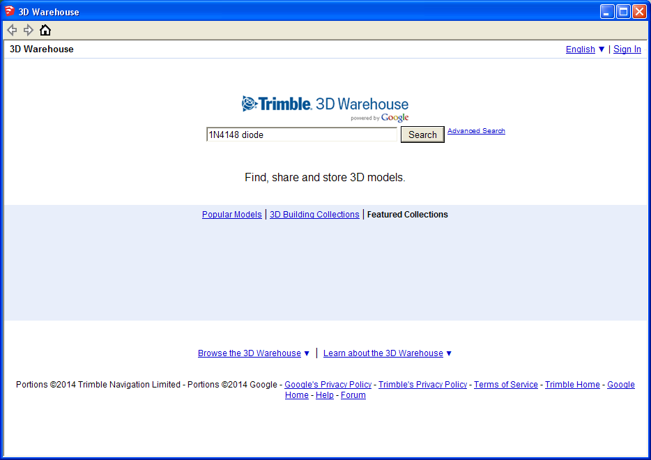
We are going to locate a suitable model for each of the missing items on the list and store them in the models folder in eagle so that all components are correctly rendered. I'm not going through every item on the list as this would be repetitive. Here is how I found a suitable model for the 1N4148 diode:
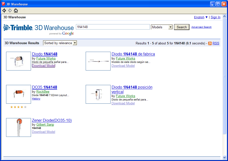
If a suitable model is available then the models will be displayed:
Click on the suitable model - in our case this would be any of the models on the left hand side. If possible download the model and save it to the models directory within program files/eagle:
Make sure you when you save the file you give it the same name as the package that was missing - in this case DIODE-1N4148. This will then store the model for use later and should ensure that the model is found next time we run the script.
In Order to save myself some time I went into eaglecad and created a bill of materials for this project. The bill of materials contains the package names for all of these parts. If I then browse the internet and locate the correct models I can then rename them to the required packages and then re-run the script - sneaky!
Once this was complete and the script has run you will be asked if you wish to re-size any of the models. I suggest you say yes as resizing them yourself is difficult and time consuming. From this point on it is a matter of moving the component models into position and aligning them and resizing as necessary. It is quite tedious work but once complete the results are spectacular and useful.
I uploaded the model I made of this PCB to Sketchup 3D warehouse - it is available for download if poeple wish to search for it:
A short distraction from the Signal Generator project to make an LC Meter Shield!
It has been a considerable time since I posted. Blogging does not come naturally for me and I often prefer to just do things rather than write about them. I still haven't finished the Signal Generator although to be honest it is close....I am lacking motivation. I have pushed that project down a route which is no longer palatable...
Instead I have decided I will write about a small project that I made recently which works well and was great fun (for me) to make and build. I always need test equipment....it's a strange thing with Engineers...they need toys to make bigger toys!
In order to measure Capacitance and Inductance a piece of test equipment is often used called an LC Meter. This is a device which measures the amount of Henries an inductor has (Henries is the unit of inductance) or the amount of Farads in a capacitor (Farads is the unit of capacitance).
Inductor - an electronic component that stores energy for a short period of time by generating a magnetic field - normally made by making a coil of wire around a former. Sometimes special cores are used to improve the inductor's frequency response. Inductors are sometimes called chokes!
Capacitor - an electronic component that stores energy for a short period of time by producing an electrostatic field on two metal plates. The size of the plates and the distance between the plates changes the amount the of capacitance the component will have. The dielectric material between the plates also has an effect of the amount of capacitance.
I needed a way of verifying that the electronic components I bought or made are within the specifications I require! Component manufacturers print the nominal level of what the inductor or capacitor is but this varies considerably between batches and is often considerably off. Every good engineer needs a way of checking that parts are what they say they are...
There are plenty of hobbyist projects available on making an LC meter. This is my interpretation. If you do a search in google for 'LC meter circuit' several pages will be sourced immediatly.
I was directly inspired by Kerry Wong's blog post -
There was also an article in Everyday Practical Electronics issue in March 2010 using a PIC Microcontroller.
I decided to make an LC Meter which uses the arduino shield form factor and is easy to make and use. I'm hoping people will like it and use it...although most electronics hobbyists I know nowadays are all digital and no analogue - ho hum!
Most LC meter instruments use a free running oscillator at a known frequency. When the user inserts the component in question in parallel with the oscilllator the frequency changes. By comparing the new frequency with the old frequency and using some mathematics the value for the component can be obtained.
So....how do we make an oscillator? There are several methods and I have discussed this in previous blog posts. This project uses a comparator to make a square wave oscillator. The circuit is below:
The oscillator section is made up of the 100uH inductor and the 4.7nF Capacitor. These two components decide the frequency of oscillation. All the other components are to make the oscillator work and to provide a method of making measurements.
The formula for calculating the frequency of oscillation and the other formulae used in the project are below:
lets calculate the frequency of our oscillator:
L = 100 uH or 100 * 10^-6 H
C = 4.7 nF or 4.7 * 10^-9 F
PI = 3.142..
So our oscillator will free run at 232 kHz using the above inductor and capacitor. If we then introduce another component into the oscillation this frequency will change and we can use the original frequency and information about the oscillator components to calculate what value the new component has.
Here is a short simulation video showing how the measurement stage works:
Now that we have a method of measuring the components we need a way of controlling the circuit and displaying the information.
To this end I am going to use the popular arduino platform because its a great piece of hardware for rapid prototyping! Here is the rest of the circuit:
The circuit is fairly boiler plate electronics. The frequency of the oscillator is measured by the arduino on pin 5. The firmware uses a special arduino frequency counter library - more on this later. The type of measurement is controlled by a switch selecting which type of component is being measured and then we also have two buttons for displaying the current frequency of oscillation or measurement function (which controls a relay) and a calibration / zero button. We finally have an 16x2 LCD display being controlled by the arduino to display the information.
Once I had prototyped the circuit and checked it worked - briefly I laid out a PCB and etched a circuit board. Here is the layout:
Top Layer with component placement
PCB Bottom Layer
I then etched and drilled the PCB and populated it with components. I was so excited I plugged it onto my arduino and tried to get it working straight away...It didn't but that's not surprising. If a project works first time nobody learns anything! Sometimes though I do wish projects would work first time - particularly at work!
The problems were minor and have been fixed in the layout so if I decide to make another version it will work first time - Here is a link to the Eagle files and other associated information:
Once I had checked that the oscillator was working with an oscilloscope I got on with writing the source code. I'm not the best programmer in the world so I used a lot of other people's work to get this circuit to work as intended. Kudos to Kerry Wong and his version of this project!
The reason this project is viable is because of the frequency counter library made and maintained by Peter Welter-Platz
Updated Library for the reading the Button presses:
Its a great library and it makes it very easy for people to measure frequency of signals with their arduino. Basically I believe the library works by comparing the frequency to be measured with one of the internal microcontroller timers. The result is then stored and available for interrogation.
In order to get the code to compile you will need to download the latest versions of these libraries and install them using the Arduino IDE.
Here is the code...it's not perfect but it does work:
/*
  Langster's LC Meter Code - 09-06-2019
  Uses the LCD library, Frequency Library
  Button libary and various other bits and pieces

  Updated the code for use with updated libraries etc.

  V2.0

  This code borrows from Kerry Wongs LC Meter
  code!

  To Calibrate press both the Frequency and
  Calibrate buttons together!

  To measure frequency press the frequency
  button

  Enjoy!

 */

// Include the Frequency counter library
#include <FreqCounter.h>

// Include the Button Library
#include <Button.h>

//part of the switch position check
enum meterMode {
    L,
    C,
    F
};

unsigned long indFreq = 23896;   //rough frequency from oscilloscope measurements
unsigned long capFreq = 23885;   //rough frequency from oscilloscope measurements

long measureComponentFreq = 0;   //variable to store component measurement frequency

float cMeasured;                 //Th measured capacitance
double lMeasured;                //The measured inductance

float cMeasuredZero;             //The zero factor for capacitance
double lMeasuredZero;            //The zero factor for inductance

//Some temporary variables for calculations

long temp1;
long temp2;
double temp3;

const float Cth = 4.7 * 1e-9;    //measured 4.7nF - calibration capacitor value
const float Lth = 91.14 * 1e-6;  //measured 91.14uH - calibration inductor value

int i=0;                         // count variable
int switchState;                 // variable for storing the state of the switch

unsigned long frq;               //The frequency measurement
long capFreqArray[10];           //An array for storing frequencies
long indFreqArray[10];           //An array for storing frequencies

long frqAverage = 0;             //An variable for averaging
long average = 0;

const int frequencyButtonPin = 16;     // the number of the pushbutton pin
const int calibrateButtonPin = 15;     // the number of the pushbutton pin
const int relayPin = 14;               // the number of the relay pin
const int componentSelectPin = 2;      // the number of the component select pin
const float pi2=6.283185307;

Button calibrationButton = Button(15);  //Calibration button on pin 15 or A1
Button frequencyButton = Button(16);    //Frequency button on pin 16 or A2

meterMode currentMode;                  //check which mode the switch is in

// include the LCD display library:
#include <LiquidCrystal.h>

// initialize the library with the numbers of the interface pins
LiquidCrystal lcd(12, 11, 10, 9, 8, 7);

//Check the switch position

void checkLCMode() {

    switchState = digitalRead(componentSelectPin);

    if (switchState==LOW) {
        currentMode = L;
        lcd.setCursor(0, 0);
        lcd.print("Mode: L    ");
        measureInductance();

    } else {
        currentMode = C;
        lcd.setCursor(0, 0);
        lcd.print("Mode: C    ");
        measureCapacitance();
    }

}

//setup the arduino

void setup() {
  // set up the LCD's number of columns and rows:
  lcd.begin(16, 2);

  pinMode(relayPin, OUTPUT);

  pinMode(calibrateButtonPin, INPUT);
  pinMode(frequencyButtonPin, INPUT);
  pinMode(componentSelectPin, INPUT);

  digitalWrite(componentSelectPin, HIGH);

  Serial.begin(57600);        // connect to the serial port
  digitalWrite(relayPin, HIGH);

  lcd.setCursor(0, 0);
  lcd.print(" ** LC Meter ** ");

  //measureCalibrationCapacitance();
  //measureCalibrationInductance();

  delay(2000);

  lcd.clear();

}

void loop()
{
  //check if calibration is required

  if(calibrationButton.pressed() && frequencyButton.pressed())
  {
    switchState = digitalRead(componentSelectPin);

    if (switchState==LOW)
      {
          currentMode = L;
          lcd.setCursor(0, 0);
          lcd.print("Short Terminals");
          lcd.setCursor(0, 1);
          lcd.print("Press Cal Button");

          if(calibrationButton.pressed())
            {
              measureCalibrationInductance();
            }

      }

    if (switchState==HIGH)

      {
          currentMode = C;
          lcd.setCursor(0, 0);
          lcd.print("Clear Terminals");
          lcd.setCursor(0, 1);
          lcd.print("Press Cal Button");

          if(calibrationButton.pressed())
            {
              measureCalibrationCapacitance();
            }
      }

  }

  //check if frequency measurement is required

  if(frequencyButton.pressed())
      {
        measureFrequency();
        digitalWrite(relayPin, HIGH);
      }

checkLCMode();    //check switch position


}

//Measure the frequency

void measureFrequency()
{

    digitalWrite(relayPin, LOW);

    FreqCounter::f_comp=10;   // Cal Value / Calibrate with professional Freq Counter
    FreqCounter::start(100);  // 100 ms Gate Time
    while (FreqCounter::f_ready == 0)
    frq=FreqCounter::f_freq;

    lcd.setCursor(0, 0);
    lcd.print("Frequency ");

    lcd.setCursor(0, 1);
    lcd.print("F: ");
    lcd.print(frq);
    lcd.print("      ");

    delay(4000);

}

//Calibrate for inductance measurements

void measureCalibrationInductance(){

    for (int i=0; i<100; i++)

        {
          FreqCounter::f_comp=10;   // Cal Value / Calibrate with professional Freq Counter
          FreqCounter::start(100);  // 100 ms Gate Time
          while (FreqCounter::f_ready == 0)
          frq=FreqCounter::f_freq;
          indFreq=frq;

          temp1 = sq(indFreq);
          temp2 = sq(measureComponentFreq);
          temp3 = float(temp1)/float(temp2);
          lMeasured = Lth*(temp3-1);
          lMeasuredZero = lMeasured;
          i++;

        }

      lcd.setCursor(0, 0);
      lcd.print("Calibration     ");
      lcd.setCursor(0, 1);
      lcd.print("Complete        ");
      delay(4000);

      lcd.clear();

}

//Measure the inductance

void measureInductance()

{
      FreqCounter::f_comp=10;   // Cal Value / Calibrate with professional Freq Counter
      FreqCounter::start(100);  // 100 ms Gate Time
      while (FreqCounter::f_ready == 0)
      frq=FreqCounter::f_freq;
      measureComponentFreq=frq;

      delay(200);

      calcIndData();

}


//Calculate and Display the Inductance

void calcIndData(){

    temp1 = sq(indFreq);
    temp2 = sq(measureComponentFreq);
    temp3 = float(temp1)/float(temp2);
    lMeasured = Lth*(temp3-1) - lMeasuredZero;

    lcd.setCursor(0, 1);
    lcd.print("L: ");

     if (lMeasured >= 1e-9 && lMeasured < 1e-6)
            {
                lMeasured = lMeasured * 1e9; // nano
                lcd.print(lMeasured);
                lcd.print(" ");
                lcd.print("nH");
                lcd.print("        ");
            }

            if (lMeasured > 1e-6 && lMeasured < 1e-3)

            {
                lMeasured = lMeasured * 1e6; // micro
                lcd.print(lMeasured);
                lcd.print(" ");
                lcd.print("uH");
                lcd.print("        ");
            }


            if (lMeasured > 1e-3)

            {
                lMeasured = lMeasured * 1e3; // milli
                lcd.print(lMeasured);
                lcd.print(" ");
                lcd.print("mH");
                lcd.print("        ");
            }

}

//Measure the Calibration Capacitance

void measureCalibrationCapacitance()
{
  for (int i=0; i<100; i++)
        {
          FreqCounter::f_comp=10;   // Cal Value / Calibrate with professional Freq Counter
          FreqCounter::start(100);  // 100 ms Gate Time
          while (FreqCounter::f_ready == 0)
          frq=FreqCounter::f_freq;
          capFreq=frq;

          temp1 = sq(capFreq);
          temp2 = sq(measureComponentFreq);
          temp3 = float(temp1)/float(temp2);
          cMeasured = Cth *(temp3-1);
          cMeasuredZero = cMeasured;
          i++;
        }

     lcd.setCursor(0, 0);
     lcd.print("Calibration     ");
     lcd.setCursor(0, 1);
     lcd.print("Complete        ");
     delay(4000);

     lcd.clear();

}


//Measure the capacitance

void measureCapacitance(){

      FreqCounter::f_comp=10;   // Cal Value / Calibrate with professional Freq Counter
      FreqCounter::start(100);  // 100 ms Gate Time
      while (FreqCounter::f_ready == 0)
      frq=FreqCounter::f_freq;
      measureComponentFreq=frq;

      delay(200);

      calcCapData();

}

//Calculate and display the capacitance

void calcCapData(){

    temp1 = sq(capFreq);
    temp2 = sq(measureComponentFreq);

    temp3 = float(temp1)/float(temp2);
    cMeasured = Cth*(temp3-1)-cMeasuredZero;

    Serial.print("Capacitor Oscillator Frequency: ");
    Serial.print(capFreq);
    Serial.println();
    Serial.print("Component Oscillator Frequency: ");
    Serial.print(measureComponentFreq);
    Serial.println();
    Serial.print("Cap Osc Squared: ");
    Serial.print(temp1);
    Serial.println();
    Serial.print("Msr Osc Squared: ");
    Serial.print(temp2);
    Serial.println();
    Serial.print("Division       : ");
    Serial.print(temp3);
    Serial.println();
    Serial.print("Component Value: ");
    Serial.print(cMeasured);
    Serial.println();


    lcd.setCursor(0, 1);
    lcd.print("C: ");

     if (cMeasured < 1e-9)
            {
                cMeasured = cMeasured * 1e12; // pico
                lcd.print(cMeasured);
                lcd.print(" ");
                lcd.print("pF");
                lcd.print("       ");
            }

     if (cMeasured >= 1e-9 && cMeasured < 1e-6)

            {
                cMeasured = cMeasured * 1e9; // n
                lcd.print(cMeasured);
                lcd.print(" ");
                lcd.print("nF");
                lcd.print("       ");
            }

      if (cMeasured > 1e-6)
            {
                lcd.print("Out of Range");
                lcd.print("        ");
            }

}
It's long and it isn't pretty but it should be fairly simple to understand. The program sets up the libraries, variables and the buttons and LCD display. It then looks at which position the user component select switch is in and then performs the required measurement. If the user presses the frequency button the current frequency of the oscillator is displayed. If the user presses and holds both buttons and then follows the on screen instructions the unit calibrates. In order to calibrate the L mode the input terminals have to be shorted together. For capacitance mode the terminals must be open and not connected to anything.
Here is a video of the completed unit running on my arduino Uno in use.
There are things about the LC meter that I would do differently - there always are! I would prefer the device to have a larger measurement range - Inductors are ok but the capacitance range of up to 1 µF is not helpful. I often like to measure electrolytic capacitors and this unit can't do that. In order to achieve that I need to implement a frequency divider circuit on the measurement frequency pin so that I can then use a smaller measurement capacitor which increases the range. I would also like to add another relay which automatically shorts the measurement terminals so that when calibrating the inductor range the user doesn't have to short the terminals. All told though this came out very well!
Update: I got some valuable feedback from a reader who asked if it would be possible to implement the analogue section using a dual comparator. It is possible and I have selected the LM393 dual comparator to do this. Here is the full schematic:
I hope this helps people make their own versions of the circuit! Here is a link to the LM311 Eagle Files:
I have had some feedback from quite a few people regarding this post...my most popular project yet! I have decided to help out by giving the bill of materials:
All of the part numbers are for Farnell Electronics. I suggest people shop around for various parts as they can be found cheaper elsewhere - particularly the 16x2 LCD display and the Arduino.
Here is some 3D renders of the circuit I made using Eagle and Sketchup! I also made a case which can be 3D printed.
Update - A lot of people have been building this project (which is great!) but are sometimes struggling to check things are working as intended. If you have access to an oscilloscope you can measure the oscillation frequency by connecting the oscilloscope probe ground lead to any 0V reference on the circuit (I use the ground plane normally) and then connect the probe tip to pin 2 of the LM339 or pin 3 of an LM311. Ensure that the measurement terminals are open (nothing is connected to them and the unit is in capacitance mode. If the same 100 uH inductor and 4.7 nF capacitor have been used it should be possible to see the following waveform:
LC Meter Oscillator on Pin 2 with terminals open
If you want you can then short the terminals together and change the select switch and you should see exactly the same waveform!
The oscilloscope was set to 5 volts / division on the Y axis and the time base was set to 2 micro-seconds per division for the X axis. The trigger level was set to 1 Volt and the channel was set to measure a DC signal. Good Luck!