You can download eagleUp 4.4 from here:
eagleUp4.4.zip
I would actually follow the instructions from the eagleUp Website though as there is more information to be found:
http://eagleup.wordpress.com/installation-and-setup/
Once you have the programs installed and setup it really is very simple to render your PCB into a 3d image so that you can view the 'populated' PCB and design mechanical enclosures ready for manufacture by 3d printing or using a laser cutter.
You will also need to obtain a copy of Sketchup Version 8
sketchup 8 download
I would install the programs as directed before continuing! You will need to follow the instructions to tell sketchup where the eagle up addon is so that it's possible to load the .eup file into sketchup. Don't worry it isn't hard!
I recently designed a version of the LC Meter for one of the blog readers using an LM311 comparator. It uses exactly the same firmware as in the previous post but instead of using an LM339 quad comparator it uses an LM311 dual comparator. The circuit works in exactly the same way as the previous version. If people wish to know how it works they should check out the previous post:
Here is the Schematic Diagram:

Here is the PCB bottom layer:

The bottom layer is mirrored here so that it can be printed ready for toner transfer to manufacture the PCB. It doesn't show whether any components are over lapping or fouling or how the top side of the PCB will look once populated with components. This is where eagleUp 4.4 comes in handy!
In the eagle PCB layout screen click on the run ULP Icon:

Now select eagleUp_export.ulp from the open dialog box:

The following window will appear:

These are the parameters which can be changed depending on your requirements:
Image Export - the amount of pixels present in the render - the higher the dpi the larger the file size and the longer it will take to render the PCB
Outline Layer - select which the layer the image will use as the dimension
Silk Layers - Select whether you wish for the silk screen to be present and to use both place diagrams and component names and identifications or not at all
Misc - Choose whether you wish to render the PCB with or with components and vias
Board Thickness - The physical thickness of the glass fibre substrate supporting the copper tracks and components
Choose solder mask color - Which colour (I'm british!) should we use for the etch resist - most people use green but OSH park like to use purple! It's up to the user...
Choose plating - what colour do you want the tracks to be....I always choose gold but again it's up to the user.
Choose silk color - What colour will the silk screen be...Again I always choose white but it's the user's choice.
When ready click Ok and wait for the magic to complete - this may take some time although for most boards it was less than 2 minutes. The PCB and components are being rendered and placed on the PCB in a sketchup image.

Load up Sketchup 8 and click on the plugins menu Item import eagleUp v4.4

Then when the dialog box appears navigate to the appropriate eagle directory for the project

Mine was callled LC Meter dif Ver...
Inside that eagle project folder there will now be a folder labelled eagleUp. Select that folder and then select the .eup file inside it.

Once you click open again be prepared for a short wait of about two minutes...the program is running a script file which is placing the components and rendering the image.
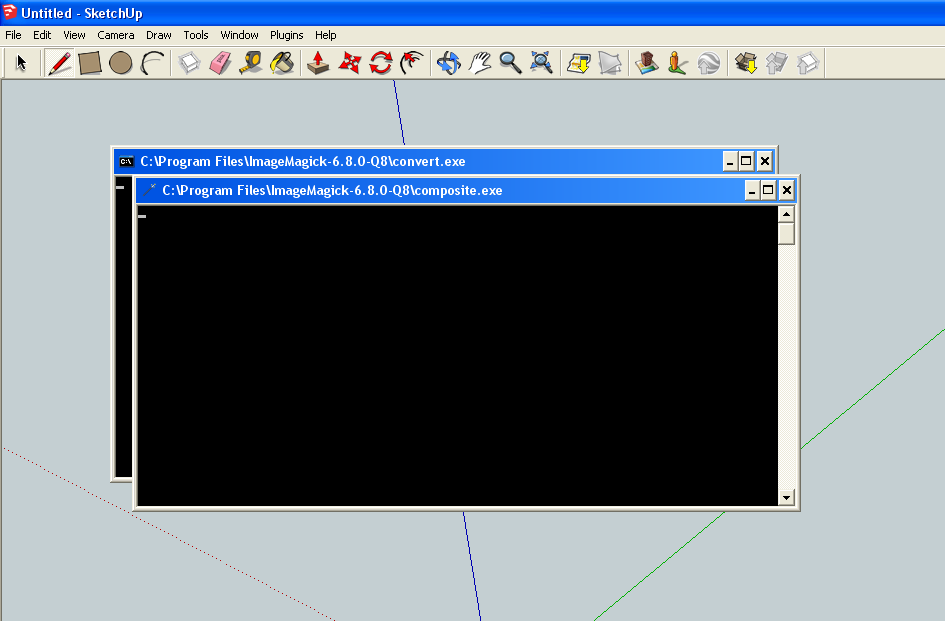

If we look closer at the dialog box it's telling us that the program did not have sketchup models with the correct names to place them on the PCB. Make a note of all of the names in the dialog box as we will need this information for later:

Click ok when ready. We are now going to find suitable models for the missing parts and then label the files with the correct names so that when if we were to re-run the import eup script all the missing items would be found and rendered correctly.
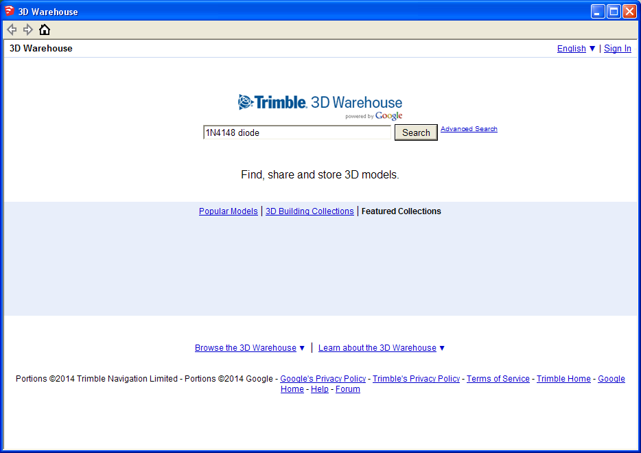
Click on the file menu in sketchup and navigate to the 3d warehouse section:

We are going to locate a suitable model for each of the missing items on the list and store them in the models folder in eagle so that all components are correctly rendered. I'm not going through every item on the list as this would be repetitive. Here is how I found a suitable model for the 1N4148 diode:
If a suitable model is available then the models will be displayed:
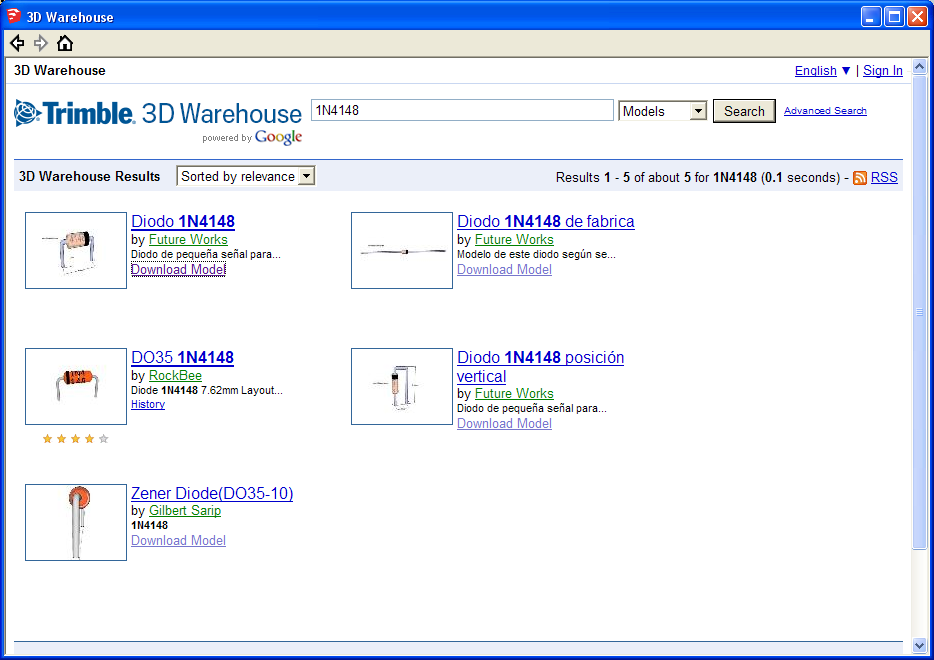
Click on the suitable model - in our case this would be any of the models on the left hand side. If possible download the model and save it to the models directory within program files/eagle:

Make sure you when you save the file you give it the same name as the package that was missing - in this case DIODE-1N4148. This will then store the model for use later and should ensure that the model is found next time we run the script.
In Order to save myself some time I went into eaglecad and created a bill of materials for this project. The bill of materials contains the package names for all of these parts. If I then browse the internet and locate the correct models I can then rename them to the required packages and then re-run the script - sneaky!
Once this was complete and the script has run you will be asked if you wish to re-size any of the models. I suggest you say yes as resizing them yourself is difficult and time consuming. From this point on it is a matter of moving the component models into position and aligning them and resizing as necessary. It is quite tedious work but once complete the results are spectacular and useful.
I uploaded the model I made of this PCB to Sketchup 3D warehouse - it is available for download if poeple wish to search for it:
3d warehouse LC Meter Model
Here are some screen shots just for fun.


Well that is about it for now - The next post will discuss how to design a case for the LM311 LC meter.
Cheers for now - Langster!
Thanks for Posting ! first time I have found a genuine post related to 3D Image Rendering
ReplyDeleteYou are welcome special lists. I intend continuing this section to show how I use the renders to perform the mechanical design required to make an enclosure for the LC meter. Thanks for checking out my blog!
Delete