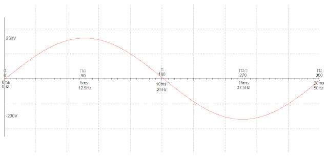
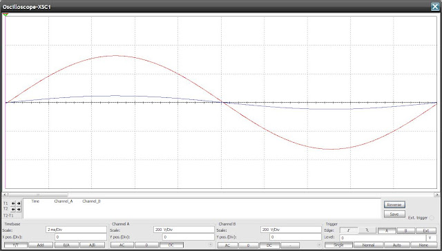
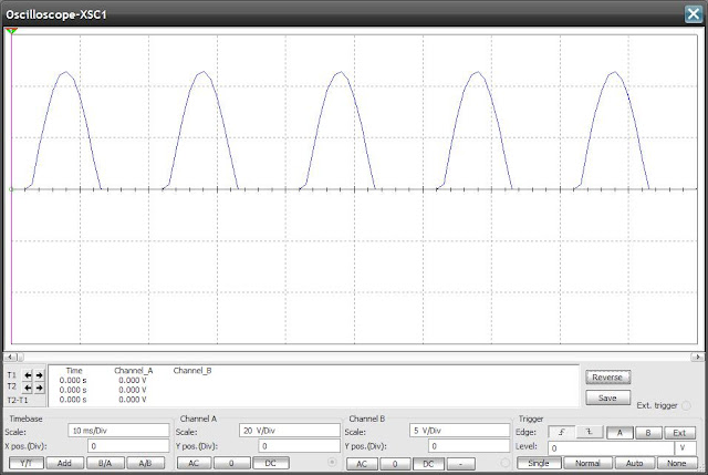
The first question one might ask is why do we need to smooth the output? One answer is because the designer is trying to replicate the output of a chemical cell (battery). The output of a battery which is direct currrent (dc) is very smooth and flat. This is because batteries work on the principle of electrolysis and electrons travel from the negative terminal to the positive terminal through the circuit in a constant stream. The flow of electrons (current) is only slowed down (resisted) by the total circuit resistance which includes the internal resistance of the battery. There is no switching or quick changes of polarity like there is with an ac power source (no 50Hz power cycle here) and because there is no switching unless introduced in the circuit on purpose (oscillation) the output of the battery will be completely smooth and flat.
Another reason for smoothing the power supply output is to prevent the circuit from reacting strangely to the constant change of voltage coming from the not smoothed supply. Suppose we have a circuit that is using a change in voltage to detect something like a temperature sensing circuit. If we use a smoothed dc supply the circuit will measure the current temperature accurately because the supply voltage is in a constant steady state. If we use a not smoothed dc supply the sensor output will fluctuate with respect the changing voltage of the supply and the sensor output would be meaningless.
The upper circuit above shows a 12.3V battery supply connected to a simple voltage divider made up of a 10k resistor and a temperature sensor. For the simulation the temperature has been set to 27 degrees C. The output voltage and current is shown in the yellow box. The output is also connected to an oscilloscope.
The lower circuit shows a 14.8V 50Hz ac supply (the output from a linear transformer secondary winding) connected to a bridge rectifier made up of four diodes. It is then connected to the same voltage divider made up of a 10k resistor and a temperature sensor. The ambient temperature is also set to 27 degrees C.
The top circuit will accurately measure the temperature because the voltage supply to the voltage divider is constant and smooth. The lower circuit's measurement will fluctuate considerably because the voltage supply to the divider is not smooth. If only the average temperature measurement is required then there would be no problem using this power supply but if the user were logging the data regularly - lets say every 1ms then the bottom circuit's measurements would be incorrect and the temperature would look to be varying with the same frequency as the power supply input.
So that is the reason that smoothing is applied to the rectified output of a linear power supply. It is to make the output constant, regular and as similar to the output of a battery as possible. It prevents strange measurement errors and erroneous circuit behaviour occurring.
In order to smooth the output from the diode rectifier section capacitors are added to the circuit across the supply. To remove the low frequency 'ripple' large value electrolytic capacitors are required. For high frequencies medium value ceramic capacitors are normally used. The large electrolytic capacitor charges up from the applied voltage from the rectifier when the output rises the capacitor charges. When the output from the rectifier lowers the capacitor then discharges. Because there is not enough of time between the rectifier output fluctuating and the capacitor charging and discharging the dc voltage output remains more constant and therefore becomes smoother. The charging / discharging time for a capacitor can be found by two formulas. I will go into more detail on the charging and discharging of capacitors in another post. The formulae are:
Vc = Vs * (1-e^-t/C*R) - For a capacitor charging
Vc = Vs * (e^-t/C*R) - for a capacitor discharging
There is a very good section on the hyperphysics website which discusses capacitors charging and discharging in the DC circuits / capacitors section - http://hyperphysics.phy-astr.gsu.edu/hbase/hframe.html
The updated circuit diagram for the linear power supply that we are designing is shown below:
It should be noted that almost any large value of electrolytic capacitor could be used and the higher the value the more low frequency 'ripple' will be removed from the power supply output. The capacitors selected must be rated to withstand the supply voltage - in our case this would be anything above 32 Volts dc. The 100nF capacitor can be of the ceramic type and should also be rated to work at voltages greater than 32V dc. The type of capacitor is related to it's dielectric material - another subject for another post.
There is a formula for selecting the smoothing capacitor to remove 10% of the ripple and it is as follows:
| Smoothing capacitor for 10% ripple, C = | 5 * Io |
| Vs * f |
C = capacitance in farads (F)
Io = output current from the supply in amps (A) - yet to be selected in our case!
Vs = supply voltage in volts (V), this is the peak value of the unsmoothed from the rectifier output
f = frequency of the AC supply in hertz (Hz)
Lets set the value of Io (current output) to 1A. If we plug in the values from our design we get:
C = 5 * 1
32 * 50
C = 0.003125 or 3125uF so the closest real value would be 3300uF which must be rated for 32V. To be on the safe side I would use a 50V rated 3300uF electrolytic capacitor. If a lower capacitance is used the ripple will be greater than 10%. The capacitor must be rated for the supply voltage!
The oscilloscope output for the smoothed and not smoothed circuit is shown below. It is pretty obvious that adding the capacitors makes the voltage output very smooth and flat which is what we were looking for. The red trace is the not smoothed rectifier output and the blue trace is the smoothed output after the capacitors.
The next post will discuss power supply regulators - what they are and how they work. That's all for now folks! Take Care - Langster!


