Showing posts with label Linear Power Supply. Show all posts

Sunday, 23 September 2012

Power Supply in the Box working!

So after some time....I have been busy again!

I have finally placed the power supply in a case and added some volt meters and checked everything works. I have also updated the circuit diagram as I wanted to reflect the extra components that I've added.  Here is the updated diagram:


I added a 3A fuse on the live side of the 230V mains input.  This is to ensure that no matter what happens at the output no more that 3A can be drawn by the power supply at the mains input.  It's purely a safety issue and in my opinion is critical.  I also added a mains rated switch so that it is possible to isolate the power supply from the mains without removing the plug from the wall socket.  Next I earthed the metal parts of the case by connecting the safety earth  from the plug to all of the metal parts of the case and finally I have added some digital voltmeters.  I bought them off ebay from this vendor although there are plenty of them around:

delhanway2009 - ebay listing

Its a standard 3 wire digital voltmeter.  I was hoping to use one as a current meter when combined with a 1 ohm resistor but that hasn't worked.  I need to investigate how these meters works....Anyway they work perfectly for displaying voltage and that is really all we need for this power supply.  When I was building the power supply I took extra care to make sure that all the wires were correctly restrained and none of the low voltage DC wires could every touch the high voltage AC wiring or exposed parts of the circuit - heatshrink and electrical tape all the way!

Here is the completed power supply below:


I'm very happy with how it came out!  It works perfectly and provides plenty of current.  I upgraded the voltage regulator to an LM338 to make sure I can get about 5A if required!  The LM338 is exactly the same voltage regulator as the LM317 but it is able to provide more current.  The datasheet for the LM338 is here:

http://www.ti.com/lit/ds/symlink/lm338.pdf

The power supply gives out at least 30V when loaded at 1A so it works well enough for all my linear power supply needs.  The regulator has built in over temperature and over-current protection so it shouldn't suffer from any of my mistakes and should last me for at least a good twenty years....Happy days!

Here is a quick video showing the power supply in operation.  I should really have connected a light bulb or something to the output to prove it works....I will upload another video later showing it powering a load.


Here is a video of the power supply driving a 12V light bulb:


That's it for now - take care always,

Alex

Saturday, 8 September 2012

Realising the Power Supply!

After months of inactivity....

I have etched the PCB for the LM317 variable power supply.  I used the design outlined in the previous post.  It seemed to come out well!  Here are some photographs of the process.


The design printed on glossy paper!


The design ready to be transferred onto the PCB - Get the clothes iron out!


The design transferred onto the PCB ready for etching!


The PCB after etching....Not too bad, some tracks were over etched.


Fanfare!!  The populated PCB, quickly switched on to see it working....I couldn't resist.

So where did things go well?  - The design was well transferred and populating the PCB was very simple.  The spacing between components was excellent!  A professional design would be much harder to put together because space is always at a premium.  Nothing smoked when I switched it on...that's always reassuring!

Where did things go wrong?  - I over etched the PCB (left it too long in the etching fluid)....It meant some of the tracks were broken.  I managed to fix this quickly with some thick braided copper wire.  I also used the wrong package size for the transformer.  I didn't check which transformer I had before I printed the PCB design.  It's a common mistake and one I won't make again for a while. I will probably change the transformer to the correct one as I may well make some of the power supplies as kits for people at my local hack space!    


The underside of the populated PCB - notice the extra holes and repairs!

The next thing to do is put the power supply in an enclosure and get some panel meters.  We need to be able to see what the output voltage and current is and we need to ensure that this is safe to use.  We don't want any accidents or mistakes when there are mains voltages and high current available!  

That's all for now people!  Take care and have fun always....

Saturday, 7 April 2012

LM317 PCB Layout

Here we go...it's PCB layout time!  Here is the schematic re-drawn and ready for PCB layout.  I have added a 5V fixed supply to the circuit because I would like to add a digital voltmeter to the circuit so we can monitor what the output voltage is set at.  After investigating panel meters on-line I found that they require a separate supply in order to work correctly.  Other than this the circuit is the same as in the previous post.


Now that we have designed the variable power supply it's time to make a printed circuit board to mount the components onto and route the connection tracks.  For PCB layout I use Eagle Cad from Cadstar because it's free up to a point, has great component libraries and support via forums from thousands of people.  

There are thousands of PCB layout tutorials for eagle available so I'm not going to go through the nuances of doing PCB layout unless requested.  I don't consider myself very good at this particular aspect of electronics.  I know the theory but I don't have much experience in the practical.  Professionally I sub-contract PCB layout out to someone else but because this is for me personally and anyone reading this the following guidelines are always good:
  • Lay out the components on a suitably sized PCB first.
  • Set the grid size to something sensible.  I used 1.27mm and 0.635mm for my grid size
  • One you have a general idea of the component location select a suitable track size.  Thicker for more current carrying capability.
  • Try not to cross tracks. 
  • Once you have all of the tracks routed perform an electrical rules check
  • Tear-drop the pads once you have completed all of the above tasks.
  • Finally resize the PCB if you can.  Less board = cheaper manufacturing costs
I shy away from auto-routing functions in PCB layout tools as they always seem to do a poor job!  I have heard of other people find these work well but I have had mixed results.  I have always found for more simple circuits it is much better to route the tracks by hand.  The PCB layout for this circuit is shown below:


I chose a thick track size on purpose as I wanted to be sure that there would be enough current carrying capacity in all of the tracks.  This might be a bit overkill but it at least it saves on copper.  I also didn't use a ground plane on this design as it isn't really necessary.

All that is left to do now is to actually make the PCB.  When I do this I use the toner transfer method of making a PCB.  That involves printing out the design in reverse (like in the above picture) on a laser printer.  I then get a piece of blank PCB.  I'm going to use a 160mm x 100mm blank PCB and cut it down to size.  I'm then going to clean the PCB thoroughly and then placing the print out of the layout ink-side down (actual size) onto the copper, and using a clothes iron, transfer the pattern.  The iron should be set to as high as possible - ENSURE there is no steam or water in the iron.  Firmly press and iron the paper for about 5 minutes.  Then switch off the iron and wait for the PCB to cool...it will be too hot to handle.  Once cooled run the PCB under water to 'soak off the paper'.  What should have occurred is that the design has transferred from the paper onto the copper of the PCB.  If it hasn't worked clean the PCB off and repeat the process.  Next etch the PCB in ferric chloride or Muriatic acid...whichever you prefer.  I use ferric chloride because I find it gives me a better etch and because Muriatic acid (Swimming Pool Cleaner) is hard to get hold of in the UK.

That's about it for now.  Next post will be the actual building and soldering of the supply with photographs!  For those that might be interested here is a good tutorial on PCB layout:

http://www.alternatezone.com/electronics/files/PCBDesignTutorialRevA.pdf - From the EEVBlog! Kudos to David L. Jones

Here are the eagle files for this project so that if people wish to make this power supply for themselves!

LM317 design files on Github

Update: I found having constructed the above circuit that there was a mistake in both the schematic and the PCB.  I have updated both to resolve the issue.  I missed out a connection on the schematic which prevented the supply from going low.  The variable resistor needs a link from the middle pin (wiper) to the top pin so that the voltage output of the LM317 can be reduced down to 1.25V


Here is the component placement in case someone needs it!

Tuesday, 3 April 2012

Power supplies part III

Still getting on with the job of designing a linear power supply!

Last post talked about smoothing and why large electrolytic capacitors are used to remove ripple.  This post is going to talk about voltage regulators.

The voltage output from the previous circuit although now nice and smooth will not be constant.  As soon as an electronic 'load' or impedance to use the proper term is placed across the positive and zero volt terminals the voltage will drop because there is not a constant current present to drive the load.  The circuit that fixes this problem is called a voltage regulator.  There are many different types of circuits for making voltage regulators and they all have their place.  I don't intend going into all the different types of regulator here.  If people are interested the web sites below maybe useful:

http://en.wikipedia.org/wiki/Power_supply#Linear_regulated_power_supply - Wikipedia!

http://www.eevblog.com/2011/11/28/eevblog-221-lab-power-supply-design-part-1/ - the excellent EEVBlog by Dave L. Jones!

http://www.allaboutcircuits.com/vol_3/chpt_9/2.html - All about circuits....I highly recommend this site!  Its
great for electronics theory.

Essentially a voltage regulator is a special circuit that provides a constant voltage to a current controlled device which keeps the output to the load constant whether the load or the supply are changing.  We know that the supply isn't constant as the transformer is supplied with an AC voltage which switches polarity every 10ms and the load attached to the output may not be constant either.

The constant voltage output is usually achieved by using a special diode called a Zener diode.  These devices are a special kind of diode which allow current to flow in both directions once a certain voltage is applied to the anode.  Zener diodes are used to provide a constant voltage reference.  Check out all about circuits page in zener diodes for more information here:

http://www.allaboutcircuits.com/vol_3/chpt_3/11.html

The next part of the regulator would be made up of a series pass transistor.  This is normally a high current transistor which is permanently switched on by the zener diode and a resistor and is used to keep the current output constant. So by implementing the circuit below we have a constant voltage regulator.  To keep the theory simple I have selected a 12V zener diode and that is what decides our output voltage for the power supply.

If we were to implement the circuit above it would provide us with a constant 12V (all right 11.643V) output whatever load was attached.  However there are better and easier ways of implementing the above circuit (Series voltage regulator) using an integrated circuit known as the three terminal voltage regulator.

There are literally hundreds of different types of three terminal linear voltage regulators - some of the more popular ones are the ubiquitous 78 series which are a fixed voltage output linear regulator.  Another might be the LT38 series.

For my power supply though I wanted an adjustable voltage output and so I'm going to use an adjustable voltage regulator - the venerable but useful LM317.  There are many manufacturers of this device but they all perform the same function.  The datasheet and application note for this regulator from Texas Instruments are here:

http://www.ti.com/lit/ds/symlink/lm117.pdf - Datasheet

The circuit will now look like this.  This circuit is directly taken from the information provided in the datasheet.  All the information needed to design the circuit is there.  Datasheets are like rosetta stones to electronics design engineers.  When they are well written they can make our lives so much simpler!


You may have noticed I have added some extra components to our circuit.  R1 is what is known as a 'bleeder' resistor.  This is so that when power is removed from the circuit the energy stored in the electrolytic capacitors is safely drained away.  Otherwise the capacitors can remain charged for a very long time and store a lot of energy which will be released when someone (normally me) shorts the output by mistake.  The diodes D4 and D3 are protection diodes for the regulator IC.  They protect the regulator from short circuits and transients caused by capacitors discharging.  The resistor R5 and the LED are for indication purposes.  Its always good to have visual indication that the power supply is switched on!  The variable resistor R3 is to allow the user to vary the output voltage from 1.25V to about 40V.  R4 is part of the voltage divider which sets the output voltage.  C4 and C6 are ripple smoothing capacitors for the output.  Finally I added a voltmeter so that we can see what the output voltage is set at when using the circuit.

Well...thats it for now folks.  More to come soon!  Enjoy and take care - Alex

Monday, 12 March 2012

Power Supplies - Part 2

In the last post I wrote about some of the design considerations that are needed in designing a linear power supply and how mains ac voltage can be 'stepped down' and rectified into dc using diodes.  The next thing that most people do when designing power supplies is called 'smoothing'.  This is where the output waveform which is regular but not flat is made more flat and smooth.

The first question one might ask is why do we need to smooth the output?  One answer is because the designer is trying to replicate the output of a chemical cell (battery).  The output of a battery which is direct currrent (dc) is very smooth and flat.  This is because batteries work on the principle of electrolysis and electrons travel from the negative terminal to the positive terminal through the circuit in a constant stream.  The flow of electrons (current) is only slowed down (resisted) by the total circuit resistance which includes the internal resistance of the battery.  There is no switching or quick changes of polarity like there is with an ac power source (no 50Hz power cycle here) and because there is no switching unless introduced in the circuit on purpose (oscillation) the output of the battery will be completely smooth and flat.

Another reason for smoothing the power supply output is to prevent the circuit from reacting strangely to the constant change of voltage coming from the not smoothed supply.  Suppose we have a circuit that is using a change in voltage to detect something like a temperature sensing circuit.  If we use a smoothed dc supply the circuit will measure the current temperature accurately because the supply voltage is in a constant steady state.  If we use a not smoothed dc supply the sensor output will fluctuate with respect the changing voltage of the supply and the sensor output would be meaningless.

The upper circuit above shows a 12.3V battery supply connected to a simple voltage divider made up of a 10k resistor and a temperature sensor.  For the simulation the temperature has been set to 27 degrees C.  The output voltage and current is shown in the yellow box.  The output is also connected to an oscilloscope.

The lower circuit shows a 14.8V 50Hz ac supply (the output from a linear transformer secondary winding) connected to a bridge rectifier made up of four diodes.  It is then connected to the same voltage divider made up of a 10k resistor and a temperature sensor.  The ambient temperature is also set to 27 degrees C.

The top circuit will accurately measure the temperature because the voltage supply to the voltage divider is constant and smooth.  The lower circuit's measurement will fluctuate considerably because the voltage supply to the divider is not smooth.  If only the average temperature measurement is required then there would be no problem using this power supply but if the user were logging the data regularly - lets say every 1ms then the bottom circuit's measurements would be incorrect and the temperature would look to be varying with the same frequency as the power supply input.


So that is the reason that smoothing is applied to the rectified output of a linear power supply.  It is to make the output constant, regular and as similar to the output of a battery as possible.  It prevents strange measurement errors and erroneous circuit behaviour occurring.

In order to smooth the output from the diode rectifier section capacitors are added to the circuit across the supply.  To remove the low frequency 'ripple' large value electrolytic capacitors are required.  For high frequencies medium value ceramic capacitors are normally used.  The large electrolytic capacitor charges up from the applied voltage from the rectifier when the output rises the capacitor charges.  When the output from the rectifier lowers the capacitor then discharges.  Because there is not enough of time between the rectifier output fluctuating and the capacitor charging and discharging the dc voltage output remains more constant and therefore becomes smoother.  The charging / discharging time for a capacitor can be found by two formulas.  I will go into more detail on the charging and discharging of capacitors in another post.  The formulae are:

Vc = Vs * (1-e^-t/C*R) - For a capacitor charging
Vc = Vs * (e^-t/C*R) - for a capacitor discharging

There is a very good section on the hyperphysics website which discusses capacitors charging and discharging in the DC circuits / capacitors section - http://hyperphysics.phy-astr.gsu.edu/hbase/hframe.html

The updated circuit diagram for the linear power supply that we are designing is shown below:

It should be noted that almost any large value of electrolytic capacitor could be used and the higher the value the more low frequency 'ripple' will be removed from the power supply output.  The capacitors selected must be rated to withstand the supply voltage - in our case this would be anything above 32 Volts dc.  The 100nF capacitor can be of the ceramic type and should also be rated to work at voltages greater than 32V dc.  The type of capacitor is related to it's dielectric material - another subject for another post.

There is a formula for selecting the smoothing capacitor to remove 10% of the ripple and it is as follows:


Smoothing capacitor for 10% ripple, C =5 * Io   
Vs * f

C  = capacitance in farads (F)
Io  = output current from the supply in amps (A) - yet to be selected in our case!
Vs = supply voltage in volts (V), this is the peak value of the unsmoothed from the rectifier output
f  = frequency of the AC supply in hertz (Hz)


Lets set the value of Io (current output) to 1A.  If we plug in the values from our design we get:

C =  5   *   1
       32 *  50

C = 0.003125 or 3125uF so the closest real value would be 3300uF which must be rated for 32V.  To be on the safe side I would use a 50V rated 3300uF electrolytic capacitor.  If a lower capacitance is used the ripple will be greater than 10%.  The capacitor must be rated for the supply voltage!

The oscilloscope output for the smoothed and not smoothed circuit is shown below.  It is pretty obvious that adding the capacitors makes the voltage output very smooth and flat which is what we were looking for.  The red trace is the not smoothed rectifier output and the blue trace is the smoothed output after the capacitors.


The next post will discuss power supply regulators - what they are and how they work.  That's all for now folks!  Take Care - Langster!


Sunday, 11 March 2012

Power Supplies! Part 1

Hi people...I know I have still to finish the chess clocks.  For now though I though I would do a post on power supplies.

I recently donated my bench top power supply to my local Hackspace - HACMan at Madlab!....As usual I then needed it to do some prototyping work.  One thing every budding electronics engineer or hardware hacker needs is a good power supply.  Rather than trek to the Hackspace to get mine back I'm going to design and build another!

There are many tutorials out there for building a power supply but seeing as I need one I thought I would write my own after having to go through it for myself.

There are some design considerations to choose before making a power supply:

  • Type - Linear or Switch-mode
  • Variable voltage or fixed
  • Variable current or fixed
  • Over current protection
  • Short Circuit protection

Most of these things are dependent on the type of regulation that is chosen.  I have decided to use a linear supply in my case.  These are power supplies which use a linear transformer - a device used to convert the ac mains voltage from 230V UK Mains voltage down to a more useful and safer low voltage.  In this case I would like a supply that has variable voltage and current control from around 3V up to 30V with at least 1A current.  I also will need a way of displaying what the actual voltage and current setting is so we will be adding some panel meters.

How do these things work?  Electricity comes out of the UK mains socket as 230V r.m.s. alternating current or ac at 50Hz.  What exactly does that mean??  Well it means that the electricity has a maximum electrical pushing force of 230V and that the polarity changes direction every 10ms or 25Hz.  For definitions on basic electrical theory and general physics here is an excellent website:


It covers everything in a lot more detail than I intend to go through in this post.  So back to the subject.....

For those who don't know electricity is generated by rotating a permanent magnet in a coil of wire.  The magnet  turns in a circular motion.  The more the magnet moves the more electricity is generated.  The speed of the magnet turning is directly related to the frequency of the current.  Every time the north and south of the magnet are reversed the current changes polarity.  The circular motion causes the output to be sinusoidal and if we were to plot a graph of the output it would look like the picture below:
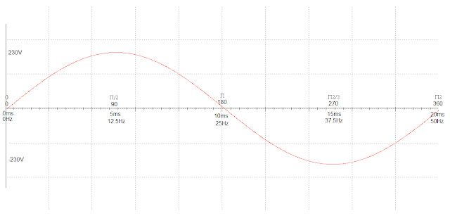
I have put several scales on the x axis so that it can be seen that the voltage changes polarity with respect to time and therefore frequency.  Frequency is the inverse of time or frequency (Hz) = 1 / time (seconds).  I also put degrees and radians on the graph as the change in polarity can also be related to angular motion (the magnet rotating in the coil).  This is known as alternating current and it is the type of waveform that would be seen if you were to take an oscilloscope and measure the output of a mains outlook socket.  (I don't recommend doing this unless you have a suitable high voltage ac scope probe!!!)

The ac waveform that comes out of the sockets will be 'stepped down' or transformed into a smaller voltage using a linear transformer.  A linear transformed is an electronic component with the symbol shown below:

It is really two inductive coils placed next to each other with a laminated iron core running through each ring.   For a step down transformer the first inductive coil known as the primary will have more turns than the second coil or secondary.  The difference between the coils is known as the turns ratio and this can be used to calculate how much the voltage will be 'stepped down'.  The formula - helpfully known as the turns ratio is as follows:

     Np : Ns = Vp : Vs    

Np = Number of turns on primary coil
Ns = Number of turns on secondary coil
Vp = Voltage at primary coil
Vs = Voltage at secondary coil

So lets use the formula to calculate the turns ratio of the transformer that I need for my 3-30V transformer.  We know that the mains voltage is 230V and we know that we want at least greater than 30V at the output.  To make things easy lets say 32V.  Lets plug those values into the formula:

Np : Ns = 230V : 32V

Set Ns = 1 and therefore

Np = 230V / 32V

If we then calculate the ratio we find that:

230/32 = 7.1875 

So from this we find that we need a transformer with a turns ratio 7:1.  This will 'transform' the mains voltage from 230Vac to 32Vac.

If we were to draw a schematic diagram of what we have done so far it would look like this:

If we were to attach an oscilloscope to the circuit and measure the input and output we would see the waveforms below:


Note: The Y scale or volts / division setting on the oscilloscope is the same for both graph traces (200V/div).  The red trace is the mains input or Vp and the blue trace is the 'stepped down' output or Vs.

Now that we have the voltage at a more manageable and safer lower level we need to convert it from alternating current (ac) to direct current (dc).  There are several methods of doing this and most of them involve using semiconductor rectification or diodes.  

The diode is an electronic component which acts like a kind of electrical gate.  It only allows electrical current to flow through it in one direction.  They are made up of something called a PN junction.  What is a PN junction?  Well this can get complicated but in its most basic form a diode or PN junction is a two pieces of silicon (or germanium) sandwiched together.  Before the two pieces of silicon were joined together they were treated in a special way in order to make one side more positive (P-type material) and one side more negative (N-type material).  The process is known as 'doping' and to make the semiconductor more positive the molecular structure of the silicon has had electrons removed to create 'holes'.  The N-type semiconductor material does not need anything added to it to make it more negative.  The silicon already has electrons present which make it negative.
The anode is the positive terminal and the cathode is the negative terminal.  We are going to use diodes to turn the ac output of the transformer secondary into direct current (dc).  The diodes will stop the current alternating and going negative.  It should be noted that diodes will only do this once they have 0.7V present at the anode.  It also means that our output circuit will lose 0.7V every time we add a diode.  In the circuit below a diode has been added to one of the transformer secondary outputs.  The resistor is purely a load for the electronic circuit (spice) simulator.


The oscilloscope output looks like this:


The output is now always positive in the positive portion of the sine wave or positive half cycle.  The negative half cycle is not present.  This is known as half-wave rectification  Adding more diodes to the circuit causes the negative portion of the sine wave to be rectified.  This is known as full-wave rectification.  To get full wave rectification for our circuit we will need to make what is called a diode bridge or bridge rectifier.  It is possible to buy bridge rectifiers as single parts but we are going to make one from four separate diodes:

The oscilloscope output will now look like this:


As can now be seen all of the output from the transformer is now positive.  If we were making a rugged battery charging circuit or we needed a dc current supply for welding we could use a circuit similar to this.  For most electronic applications the output will need to be smoother and more like the output of a battery.

Well....That's all for now folks.  The next post will go through smoothing and regulation!  The final post will go through realising the circuit and actually building the power supply.  Have fun as much as possible but be careful!!!